We break down series and parallel circuits, covering resistor calculations, current flow, and voltage measurement using ammeters and voltmeters. Understand the key differences and master circuit analysis. Our explanation avoids any 'bad words'.
Show More Show Less View Video Transcript
0:00
the exam questions will in most cases
0:02
have a circuit comprising of a
0:03
combination of components connected in
0:05
series and or or parallel start by
0:09
identifying which resistors are
0:10
connected in parallel and which are
0:12
connected in series when calculating the
0:14
sum of resistors in parallel make sure
0:16
you do not make the mistake of omitting
0:18
to take the reciprocal of the total
0:20
resistance as 1 / total resistance RT
0:23
equals to 1 / R1 + 1 / R2 + 1 / R3 plus
0:28
infinity depending on how many resistors
0:30
are connected in parallel for series
0:32
resistors the total resistance as RT
0:35
equals is equals to R1 + R2 + R3 +
0:39
infinity current so an ammeter measures
0:42
the current in electric circuit in
0:44
ampers a hence the flow of charges that
0:46
pass through it current is the rate of
0:48
flow of charge these simply means that
0:50
the ammeter will measure the flow of
0:52
charge per second the wires inside the
0:54
emmeter must be of negligible resistance
0:56
parallel resistors divide the current I
0:59
proportionally so the bigger the
1:01
resistor the lower the current flow the
1:03
smaller the resistor the bigger the
1:05
current flow that is current in parallel
1:07
resistors is given by the formula total
1:10
current I total equals 2 current in
1:12
amter 1 I1 plus voltage the voltage of a
1:15
battery is measured using the voltmeter
1:17
and the measuring of a voltage is volts
1:20
so a voltmeter measures the voltage in
1:22
an electric circuit in volts a hence the
1:24
flow of charges that pass through it is
1:26
negligible as we previously that current
1:28
is the rate of flow of charge these
1:30
simply means that the voltmeter measures
1:33
the potential difference as the energy
1:35
delivered across each resistor voltmeter
1:38
is constructed in such a way that it has
1:39
a very high resistance so that no
1:41
current or negligible current can flow
1:43
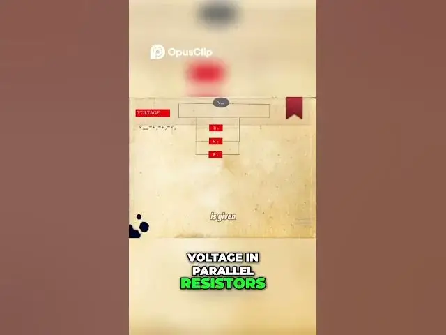
through it voltage in parallel resistors
1:45
is given by the formula total potential
1:48
difference V total equals 2 voltage in
1:51
voltmeter 1 V1 which is equals to
1:53
voltage in voltmeter 2 which is also
1:56
equals to voltage in voltmeter 3 thus
1:58
voltmeters in parallel have equal
2:00
potential difference throughout
2:01
potential difference in series resistors
2:04
divide the voltage V proportionally so
2:06
the bigger the resistor the lower the
2:09
potential difference the smaller the
2:11
resistor the bigger the potential
2:12
difference that is potential difference
2:14
in series resistors is given by the
2:16
formula total voltage I total equals 2
2:20
voltage in voltmeter 1 V1 plus voltage
2:22
in voltmeter 2 V2 plus voltage in
2:25
voltmeter 3 V3 while series resistors
2:28
have equal potential difference V hints
2:30
as said and shown on the slide
2:32
voltmeters in parallel have equal
2:33
potential difference throughout whereas
2:35
voltmeters in parallel have the total
2:38
potential difference equals to the sum
2:40
of the voltage of each voltmeter
2:41
connected in parallel don't get confused
2:44
this with current emmeters in series
2:46
have equal current throughout whereas
2:48
emters in parallel have the total
2:49
current equals to the sum of the current
2:51
of each emter connected in parallel but
2:53
for potential difference voltmeters in
2:56
parallel have equal potential
#Science
#Physics


