Up next in 10


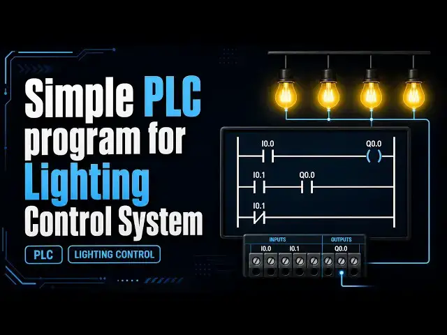
Simple PLC program for Lighting Control System Learn in this video.
#simple #lighting #program
Show More Show Less View Video Transcript
0:06
Hello everyone, welcome to automation
0:08
community. Today in this video we are
0:12
going to discuss about an example in
0:14
which we will control four lights using
0:17
a single toggle switch. So for this
0:20
example we will be using memory bit and
0:23
we will be also implementing logic. So
0:27
let's start. Example eight. If toggle
0:30
switch one is on, then light one, light
0:33
two, light three, and light four will be
0:35
on. If toggle switch one is off, then
0:38
light one, light two, light three, and
0:40
light four will be still on. That means
0:43
when we turn on toggle switch one, all
0:45
the lights turn on. And when we turn off
0:48
that toggle switch, the lights do not
0:50
turn off. All the lights remain off. So
0:54
for this example we will implement
0:57
latching so that all the lights remain
1:00
on even when we turn off the toggle
1:02
switch one and then we will be also
1:05
using a memory bit that we will latch
1:08
and that will make all the lights remain
1:12
off. So let's move to codices where we
1:15
will draw the ladder diagram for this
1:17
example and also use memory widths and
1:20
implement latching.
1:22
So I will open cortices.
1:34
Let's create a new project.
1:37
Keep the template as standard project.
1:40
You can also
1:42
you know change the location where you
1:43
want to save this file. Click on okay.
1:48
And after that choose the PLC
1:50
programming. We will be using ladder
1:53
logic diagram and click on okay.
1:58
Now let's go to here PLC programming and
2:01
here we will draw the ladder diagram. So
2:03
firstly we will insert a normally open
2:06
contact here and this will be toggle
2:10
switch
2:12
one.
2:14
Okay. And then we will be using a coil
2:19
for a memory bit. And this will be
2:22
memory bit.
2:25
And we will latch this memory bit here.
2:28
So we will insert a contact parallel
2:32
below this toggle switch one. You can
2:35
see this option here insert contact
2:37
parallel and below is written in the
2:40
bracket. So if we need to you know
2:43
insert a contact parallel but above then
2:46
we have one more option here. Here it is
2:49
option above. So we will use this
2:52
normally open contact for this memory
2:54
bit and in this way we have implemented
2:58
logic. So what happens is that when
3:02
toggle switch one is turned on this
3:04
memory bit gets through and when toggle
3:07
switch one is turned off this memory bit
3:10
should have been turned off but in ap
3:12
but due to this latching this memory bit
3:16
remains on and we will use this memory
3:18
bit to make four lights on and after
3:23
turning off toggle switch one the lights
3:25
will remain on. So we will insert uh a
3:30
network but below here and then use this
3:34
memory bit as normally open contact
3:37
here. So this will be memory
3:41
sorry
3:43
memory bit
3:46
and then we need to insert four coils
3:48
for four lines. So
3:52
we will insert coils here.
4:04
Insert a coil here and this coil will be
4:07
for light one.
4:11
Okay. And we need to insert branch below
4:14
this
4:16
and insert a coil for light two.
4:21
This is light two. Okay. And we need to
4:25
insert one more branch here.
4:29
Click here. Add. Insert branch below.
4:33
And insert a coil for light three. So
4:36
this will be light three.
4:39
Okay. And then we need to insert one
4:42
more branch here
4:47
and insert a coil. So this will be light
4:50
four.
4:54
So when toggle switch one is turned on
4:57
the signal will pass through this as a
5:00
result this memory bit gets true and we
5:03
have used this memory bit here as
5:05
normally open contact. So our turning on
5:08
this toggle switch one memory bit gets
5:10
true and when this gets true this as a
5:13
normally open contact will allow signal
5:16
to pass through this as a result this
5:18
light one light two light three and
5:21
light four all the lights turn on and
5:24
then when we turn off this toggle switch
5:27
one the signal will not pass through
5:30
this as a result this memory bit should
5:33
turn off but due to latching Here
5:37
the signal will pass through this. As a
5:40
result, this memory bit still remains
5:42
on. And when memory bit is still on,
5:46
even when this toggle switch one is
5:48
turned off, the signal will pass through
5:50
this. As a result, this light one, light
5:53
two, light three, and light four remains
5:56
on. All the light remains on even when
6:00
we turn off this toggle switch.
6:03
So let's generate code for this.
6:07
Go to online and start simulation.
6:11
After starting simulation, we need to
6:14
click on login. Yes.
6:20
And then we need to click here to start.
6:23
So as you can see here this toggle
6:25
switch is uh initially false. So all the
6:29
lights are are off. So we need to turn
6:31
on this toggle switch. We will click
6:33
here to make it through. And then let's
6:36
debug it and click on write values. And
6:39
you can see here and toggle switch one
6:41
has been turned on. We turned it on. And
6:44
then you can see memory bit gets true
6:46
because the signal passes through this.
6:49
As a result this memory bit gets true.
6:52
And when this memory bit gets true, the
6:55
signal also passes through this because
6:57
we have used the same memory bit here.
6:59
the signal passes through this because
7:02
this memory bit is true. Why? Because
7:04
toggle switch one will turn through this
7:06
memory bit. So this light one, light
7:09
two, light three and light four are uh
7:12
all are true. So light one, light two,
7:16
light three all are on. And then when we
7:20
turn off the toggle switch one, we need
7:22
to click here when it becomes false
7:24
here. And then we need to debug it and
7:27
write values. You can see here toggle
7:29
switch one the state of toggle switch
7:31
one is false. We have turned it off the
7:33
the signal doesn't pass through this but
7:36
due to latching the signal passes
7:38
through this. As a result this memory
7:40
bit still remains true. It is still on
7:43
and you can see here we have used the
7:45
same memory bit as normally closed and
7:48
normally open contact here. So the
7:51
signal also passes through this. As a
7:53
result, this light one, light two, light
7:55
three and light four, all the lights are
7:58
still on. So in short, when toggle
8:01
switch one is turned on, all the lights
8:03
gets on and when toggle switch one is
8:05
turned off, all the lights still remain
8:08
on. It was all about this example. Thank
8:11
you for watching.
8:17
>> [music]
Jobs & Education