live_tv
Livestream Starting Soon
00
Hours
:
00
Minutes
:
00
Seconds
Up next in 10

#freecad #freecaddrawing #freecadpartdesign
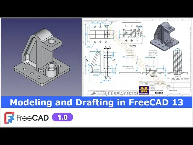
In this video I have explained How to do Modeling and Drafting in FreeCAD.
▶️ Visit my website for more info on FreeCAD-:
https://mechnexus.com/
▶️ Get my FreeCAD Crash Course for beginner-:
https://www.udemy.com/course/freecad-course-for-beginner/?referralCode=3BA9B526A12F96295D44
▶️ Download Source File of Tutorial-:
https://mechnexus.com/mechnexus-youtube-tutorial-source-file/
▶️ Buy Me a Coffee
I am very grateful that you watch my videos and I am constantly trying to improve the quality of the videos on this channel. If you'd like to help me do this, please consider supporting me so that I can to continue to produce content for your enjoyment.
👉 Help support this channel by buying me a coffee: https://ko-fi.com/mechnexus
All donations will be used to purchase equipment to improve my productivity and increase the quality of the content that I produce. Your kind support will help to grow this channel. Even if it's just enough to buy me a coffee every little helps and this will be repaid in full through my sharing of knowledge.
Show More Show Less View Video Transcript
0:00
Hello friends welcome to fre tutorial and in this tutorial we will model this part with respect to this orthographic
0:07
View and uh you can see that uh I have already created it in a freead and I
0:13
have also created a drawing now you can see that
0:21
uh we have successfully made this model in a freeat
0:27
and now I will show you from the scratch how you can model this part so I will
0:32
close this file and create a new file you can also visit my website Mach nexus.com where I write articles and
0:40
tutorials on freead you can download my tutorial source file from here tutorial
0:47
source file page and you can also support me by buying a cup of coffee on
0:55
kofi.com your uh small support will help these channels to grow and it will
1:01
motivate me to create more awesome content on fread I thanks to all my
1:06
supporter those who have supported me by buying a cup of
1:12
coffee so keep supporting and uh it will help me to grow this Channel and it will
1:20
motivate me to create more awesome and useful tutorials on freeat so let's come
1:26
back to our tutorial here I have created a new file and
1:33
now we will insert a body and on our origin plane and we will select this top
1:39
plane to create our first sketch and
1:45
now I will uh off this origin plane and I will select a rectangle
1:53
tool and we will first create this uh base
1:58
plate now I will make this symmetric so I will use the symmetricity constraint
2:04
select this point this point and axis select smart
2:09
Dimension and provide the dimension
2:15
160 by 160 so here is a 160 and here is a
2:21
160 so here I will give it 160 so our brace profile is fully
2:28
constrained and uh now I will come out of the sketch and uh
2:35
create our Extrusion so select the sketch and click on the pad and provide the pad thickness
2:42
of 10 mm which we can see here and say
2:50
okay now I will place my model to the isometric View and On the Origin plane
2:58
and I will select this this mid plane and create a sketch and uh off this
3:04
origin plane and from here I will switch to the
3:10
wireframe view and first thing which I will do is to
3:16
create projected age and now I will uh select a polyline
3:22
tool select a line tool and uh create a rough profile
3:37
Escape now I will select the line tool create a vertical
3:42
line and I will select uh 3point
3:48
Arc and uh create one
3:53
Arc just approximate and now uh with the help of a line tool I will will join
4:00
this with this now here this line is not horizontal so I will make it
4:07
horizontal and select this and uh this and add a
4:13
tangency select smart Dimension and this is the radius
4:20
40 and total height is of uh
4:28
160 and and this is of a
4:33
50 and this is of
4:41
100 and now I will move this
4:48
line and here I will delete this
4:54
line select the line tool
5:01
join it now select the
5:08
dimension give it 1 mm and this is off a
5:15
30 here is a 30 now let's uh move to this
5:23
view so here
5:30
it is a 160 because I have a given from this
5:36
age so let's uh delete
5:41
it select smart Dimension and uh from bottom to this axis is of
5:52
160 and now this center radius Center from the
6:00
origin is of uh 79.3 and uh
6:07
horizontal is of uh
6:13
134.4 and from the bottom of the H to this
6:19
point is of 50 mm and now if you see up to here it is
6:28
constraint but this is not constrain because this and this will be
6:34
equal 50 mm 50 mm so I will select this line and this line and made it equal and
6:41
now I will move this
6:48
Dimension so our profile is fully constrained and you can see the all the
6:53
dimensions let's come out of the sketch and from here let's switch to the
6:58
Shaded View and now we will uh extrude
7:06
it to the 60 mm so if you see in a top view here is a
7:13
60 mm is given go to the model
7:21
tab select the sketch click on the pad give the 60 mm and uh keep it s
7:29
metric to the plane and say okay
7:36
now if you see here here is
7:42
R30 so I will select this two age by pressing the control key and give the
7:49
fillet and here I will give 29.99
8:02
Let's uh cancel it select the fet select this hede and this
8:12
age so it is a 30 so it will be 49.99
8:31
so here if you see it is up coming 1 mm so I will go to the my
8:38
pad and uh I will delete
8:46
it and now I will give the 1 mm
8:56
inside now I will select this to age and click on the fillet and give
9:05
29.99 so you can see that the fillet has been
9:10
created and now move to the next step if you see the isometric view here
9:16
so there is a cut this cut detail we can see
9:22
here so I will uh select the face and click on the
9:27
sketch and here I will switch to the wireframe view and
9:33
I will click on the project geometry and project this age I will also project
9:39
this uh line and Arc and also this one now I will create a
9:46
line and then I will create a three-point Arc now I will select this and this and
9:55
add a tangency and select this and this and add a
10:00
parallelity and now I will select a line tool create a vertical
10:07
line and now I will uh create a vertical
10:15
line here as well and now with the help of a line
10:22
tool I will uh close my profile now let's give the dimension so here we can
10:28
see that it is a 10 mm so I will select the smart Dimension select this and uh origin and
10:38
uh give the 10 mm and this is a
10:43
69.3 so I will select this and this give it a
10:51
69.3 and now let's move this
10:57
Dimension and here here if you
11:03
see we will select this and this and add a coincidence
11:08
relation and we will fix the center point select a smart
11:14
Dimension and from the bottom of the axis so it is a
11:20
134.4 let's cancel it it's already constraint and
11:27
now this is the 10 mm align
11:33
Dimension so our profile is fully constrained let's move the
11:39
dimensions so this is the profile now close
11:47
it now switch to the flat lines and now we will create a
11:53
cut which is of a 20 mm and which we can see here
11:59
in this section view
12:05
now select the sketch click on the cut and uh say 20 mm click on okay now if
12:16
you see in our isometric view so on the other side there will be the same cut so
12:23
I will select the pocket click on the mirror and from here I will use to
12:28
select reference and select this uh plane and you can see that cut has been
12:35
created say okay now let's move to the next feature
12:43
which is to provide a fillet so here we can see that uh fillet of r10 typ means uh this and
12:53
this and other side is of a 10 mm fillet at this location this location and this location so I will select the fillet
13:01
tool and provide my fillet size 10 mm select uh this
13:10
H this
13:15
H so once you select the age it should be
13:20
added select this select uh this one and same way we
13:28
will will also select on the other site this age this age and
13:38
uh this age now we will say
13:43
okay so you can see that a fillet has been added
13:50
now let's move to the next feature so here in uh isometric view we
13:58
can uh see the cut whose detail is given in this view so it is a 30 40 and 20 so I
14:10
will select the face and uh click on the sketch and
14:16
here I will project this age click on the project geometry and project this
14:23
age and from here I will switch to the wireframe and I simply
14:30
simply create a rectangle and now I will give it a 30
14:38
mm and height is of 20 and uh from this
14:48
age it is a 40 mm so let's give the 40 mm so this is the fully constrained
14:56
sketch now I will come out of it now switch to the flat
15:04
lines now I will select the sketch click on the cut and uh this is of a cut of a
15:11
5 mm I will say okay and now here is
15:17
a R5 at four locations so I will select a
15:27
fillet I select the fillet options select this
15:36
age this
15:43
ede this age and this H and here is a fillet of
15:51
R5 give the value 5 mm click on
15:57
okay so you can see the that fillet has been applied and this feature will be
16:02
the mirror on the other side so we will first select the pocket and then select the mirror uh fillet and then click on
16:10
the mirror and here I will select my own
16:18
reference and I will select this mid plane so you can see that uh our
16:26
fillet and cut got mirror on the other side so let's
16:33
okay now let's move to the next feature if you see in isometric we will
16:39
add this pad so for this I will uh select this pH and uh click on the
16:47
sketch and here I will project this radius so click on Project
16:54
geometry and here I will uh create a cir on this
17:01
axis and now I will select this smart dimensions and here I will switch to the
17:09
wireframe select this point and this point and give the distance of a 4 mm
17:16
and uh diameter is off of
17:22
44 now it is a pad of a 5mm which we can see here and the center offset
17:28
dimensions which we can see here so it is a 4 mm offset now close it and
17:35
now switch to the flat lines and so
17:48
here so here it is going 4 mm and that
17:53
side Let's uh delete this and uh move
17:58
move it let's move to the
18:06
top switch to the wireframe so this is the 4 mm on this
18:14
side click on close and now switch to the flight lines
18:21
select the sketch click on the pad and uh this is the pad of 5mm which
18:27
we can see here so give the value 5mm click on okay and now let's uh
18:36
create our next feature if you see in this
18:43
section so same pad of a 5mm on this phas so I will select this phas and
18:50
click on the sketch and switch to the isometric view
18:55
now click on the project geometry and project this diam meter on this surface
19:01
and now switch to the bottom View and from here switch to the
19:06
wireframe and uh create a circle now select this circle and this
19:14
projected diameter and made it equal and close it and now switch to the flat
19:22
lines you can get a shortcut from here what is a shortcut for the flat line and
19:27
wireframe select the sketch click on the pad and uh this is the pad of a 5mm and
19:35
say okay now switch our model to the isometric
19:48
view now let's see so here we have provided the fillet
19:55
at this uh locations now if you see here there is a fillet in a inside of a 10 mm
20:02
so I will select the fillet and select this one of the H on both the
20:13
sides and now here I will give the value of uh 10 mm and uh let's say
20:22
okay so beautiful thing about the fillet is that it automatically added the
20:28
tangent see propagations on both the sides and created my fillet now let's move to the
20:35
next feature our next feature is to create a
20:40
cut so we can see that uh in this section View at a distance
20:48
25 so we can do one thing we can uh select
20:53
this phase and create a sketch so if you see here here so this is a 30 40 and
21:02
45 and in 45 we minus 25 and we will directly create a cut or
21:09
we can insert a DAT temp plate from the bottom so let's uh we will insert a datm
21:16
plane because it will be parametric so that once I switch the plane my cut depth will be get modified so in Z
21:24
Direction I will uh give - 25
21:30
and click on okay now I will select this plane and click on the
21:36
sketch and I will uh switch to the isometric switch to the
21:42
top and here I will project this
21:49
diameter and switch to the top view and uh switch to the
21:57
wireframe now now here if you
22:02
see the diameter size is of uh 30 so I
22:08
will select the circle tool create a circle and select smart
22:14
Dimension and give it a 30 and
22:21
now this hole is of through so I will close it
22:28
I will close it and switch to the flight lines and I will select the sketch and
22:37
create on the cut and I will say it through
22:42
all so you can see that hole has been created and now I
22:49
will off this Statum plane
22:55
now let's move to the next feature which is if you see on this uh face our
23:04
base plate face so there is a hole whose Dimension we can get uh from
23:10
here so I will select this face and uh click on the
23:16
sketch and now I will uh switch to the wireframe
23:22
view let's switch to the wireframe and here I will uh create a
23:29
rectangle and uh first thing which I will do is to make this as a
23:35
construction and this is a symmetric 110 so I will use the symmetricity
23:43
constraints like this and this and uh say okay and now I will uh give the
23:52
diamension which is of 110 and now if you see 40 40 is 80 so I
24:01
will give it a 80 mm and from this to the
24:10
origin is of 40
24:16
mm so 40 and 40 40 80 and 110 and now I
24:22
will select a circle tool create a four Circle at Four Points
24:32
and I will constraint this one of the circle with a
24:38
diameter which is of a 12 mm with a 12 mm say okay and
24:47
now I will uh press the control key and make all these
24:53
equal and now there is a hole at the center so I will create two more more
24:59
holes at this and Here and
25:04
Now select the dimension tool and give it a 40
25:11
mm and select this Center points and this Center points and add a vertical
25:16
relation and now select this circle this circle and
25:22
this circle and made it equal and click on close
25:28
and now we will create a cut Let's uh switch
25:33
to the flat
25:39
lines select the sketch click on the
25:45
cut and uh say it through all and say
25:53
okay so here I have made this hole with a cut tool you can also use the hole
25:59
feature now if you see the top view so there are
26:05
the fillet at Four Corners so I will provide a fillet of a
26:11
four corner of 10 mm I will select the face and select this
26:20
age this age this age
26:30
and this age give the value 10
26:36
mm fill it is created now switch to the isometric
26:42
view so you can see that we have successfully
26:48
converted this orthographic view into the 3D model and our model view is
26:55
matching with isometric view now we it will uh create its uh drawing so let's
27:01
save our part first we have inserted our template and
27:09
now we will place our first view I will switch to the model and select my body
27:15
and uh click on this projection group and I will select site and uh top
27:23
you say okay and now I will uh select my front
27:31
view and move it and uh lock the
27:40
position I will select this View and set lock select this View and set lock and
27:48
now I will on the hidden line and I will say it hard hidden is of
27:54
true and now as our section A is passing
28:02
through the center lines so I will enter the center line by selecting these two
28:10
lines and add a Center Line say
28:15
Okay similarly here select this and this and select and add a Center Line say
28:23
okay and now I will select my this View and click on the sections and I will
28:30
select this options and label my section A and from
28:37
here click on the live updates so here is our sections so first
28:47
we will say okay now we wanted to move our uh
28:54
sections from here to here so let's first measure the
29:04
distance select this point and this Center Line and set it horizontal Dimension so
29:13
53. 71 we wanted to move let's delete it
29:18
dimensions and now go to the section
29:26
View and uh click on the live updates in X direction we will enter
29:33
53. 71 say enter so you can see that
29:41
our Center Line is shifted now let's edit
29:48
it and uh let's decrease by 1 mm
29:59
let's make a 133 round
30:10
off okay so that is the perfectly passing through the center line and
30:16
uh say okay now we will uh place our this section
30:26
view to this
30:31
side and lock it select it and uh we will lock it but
30:41
we want to move our this front view to the position and now set it lock
30:51
so we have plac this section view now let's place this two section view so we
30:56
have placed section A8 now we will place the section BB so we will select this front view
31:04
click on the sections and this time we will select this and give the section
31:12
BB and uh click on the live
31:18
updates and uh we will say
31:24
okay now we will place our section BB
31:31
here and there is a one more sections so first I will lock it then
31:38
there is a one more section section A B B and section
31:44
CC so select it and uh click on the section select this
31:52
option and give the C and uh click on the live
32:02
updates so section is inserted now we will uh say
32:09
okay and we want to shift our section view from here to here so let's select
32:17
these two points and give the horizontal Dimension so we want to move it to the approximate
32:26
more than 15 mm Lo so let's measure this so this is the 20 so we will make shift
32:33
to the 26 mm now I will select this section we
32:41
section CC and uh click on live update in X
32:48
directions I will add the distance 26 and click on update now so you can
32:55
see that section cc is sh shift it now say okay now Zoom it our drawing and we will
33:03
uh place our uh section view
33:12
Here and Now to create some space here for the isometric view we will shift
33:22
our base view to this side and I will also move this
33:30
but I will unlock it then I can move it so I will move it here I will
33:38
also unlock it let's move
33:44
it unlock it move
33:52
it and also move this
34:05
now I will select this section BB set it lock this right view set it lock section
34:13
A a set it lock section CC set it lock
34:18
now let's uh give the dimensions so total Dimension is a
34:25
160 so I will press the control key select these two points and from here
34:32
select a horizontal dimension of 160 and this is a 30 and 40 so I will
34:41
select this point and this point provide the horizontal dimension of uh
34:48
30 and now select this point and this point and select a
34:55
horizontal dimension of 40 mm and let's move this Dimension
35:03
160 and now here is a R5 at
35:11
4X 1 2 3 4 so I will select the dimension and select this
35:19
uh radius and select R5
35:27
and uh go to the format specifications and in
35:33
bracket type
35:41
4X and
35:47
uh we will also provide the fillet here select it select uh radius and here
35:56
I will uh say it r10 typ means typical
36:02
which means that uh all the radius here is of R
36:15
10 typ now here is a dimension 48 is
36:24
given so select it select this so here is a
36:34
fillet here I have not provided the fillet that's why my Dimension is coming 50 and now from the bottom to this face
36:42
is off a 134.4 so I will select this point and
36:49
this point and add uh vertical
36:55
Dimensions so that's okay okay
37:01
135.5 now we will uh move our front
37:09
view now here is a 50/50 mm Dimensions so select this and this and
37:17
provide the horizontal Dimension 50 and here is also
37:23
50 so we will select this vertical line and this point points and provide the
37:29
horizontal dimension of 50 and total height is of 150 so select this
37:37
point and uh this
37:44
point so here it is off a 160 from the bottom and
37:51
here it is a 150 so okay now I will select this point and this
37:58
point and add a vertical dimension of a
38:09
20 Let's uh move our
38:15
view and here is a 20 mm so I will select this
38:21
point in this point and uh from here I will select get uh vertical
38:28
dimension of a 20
38:34
mm and here is of a thickness of a 10
38:39
mm this one from this cut so I will select this line and this
38:46
line and I will select the horizontal Dimension provide the 10 mm and this is
38:53
a 69.3 select this line and this line and select the horizontal
39:04
Dimension not from here it is from this
39:11
point this point to this one set a horizontal
39:18
Dimension 69.3 and uh from this s to this is of a
39:26
79.3 so so I will select this line and this line and add a horizontal
39:33
dimension of uh
39:43
79.3 so we have completed the dimension of our front view and now let's uh move
39:50
to the top view in the top view first the dimension
39:56
I will give the is 110 I will select the whole points and give the vertical
40:05
Dimension and uh I will provide the symmetricity
40:12
symbol so that this Dimension is a symmetric and at the same times I will
40:18
uh also insert a Center Line select this line and this line and
40:27
uh add a center
40:32
line and now I will provide the total width select this line and this line and
40:40
add a vertical dimension of
40:52
160 and now Define this whole positions
40:59
select this uh line and this Center and provide the horizontal dimension of a
41:06
40 select this Center and this Center provide the horizontal dimension
41:13
of a
41:20
40 and from this to this provide the horizontal dimension of
41:28
a 40 and we will also Define this 13 mm
41:33
Dimension from this to this provide the dimension of 13 mm now
41:43
decrease its Precision select and decrease
41:53
it now this is the 60 which which is a
41:59
symmetric so I will here select uh this point and this
42:05
point and add a vertical dimension of 60 and uh add a
42:15
equal constraint and now I will off my frame
42:21
and I will insert a center marks select it and insert the center
42:27
marks let's check whether we can enter a center marks at uh multiple selections
42:35
so select all these uh circles and place the center marks
42:40
yes we can and now click and add a center
42:47
marks now on the frame and
42:52
uh select the section BB and uh unlock it and uh shift it little
43:02
bit and uh again lock it and now we will provide the
43:11
dimensions so this Center to this Center provide a horizontal
43:19
dimension of a 4 mm and let's uh create a center mark
43:29
and this is the radius of a 30 mm select
43:34
it and uh select the
43:41
radius and here we will uh round off
43:54
it we will decrease the decimal places
44:06
okay now select this and uh
44:15
this let's provide the horizontal
44:21
Dimension and let's decrease it say decrease
44:27
now this is a r10 of a typical type but I will also mention in this uh section
44:34
View and uh this is a 60 and now here I will uh provide this
44:43
thickness I will select this and this and this is of 20
44:49
mm and here I will insert a center line I will select this line and and uh
44:58
this line and add a center line and uh say
45:08
okay now I will select this 20 Dimension move it and I will provide the
45:14
symmetricity constraint say
45:22
okay now
45:27
we will move to the
45:32
section section CC and here I will first insert a Center
45:38
Line select this and this and let's add
45:43
a Center Line say okay and now here I will provide the
45:49
additional Dimension select this and this and
45:54
provide the horizontal dimension
46:05
and now I will select this point and this point and add a horizontal
46:15
Dimension so here is of uh 50 mm so here
46:21
we will increase our cut to the 10 10 mm so we will go to our
46:29
model and uh we will modify our
46:35
model Let's uh go to the
46:40
pocket let's check it which pocket it
46:47
is so it is this pocket so here I will go
46:53
edit so we are getting a 50 mm which means that
46:59
let's um make it 15 mm let's say
47:11
Okay so let's solve it and
47:16
now switch to the model Tab and uh activate the last feature and now let's
47:22
check on the drawing view so this is the 30
47:29
now we will uh make it symmetric we will move this
47:35
dimensions and here I will provide the equal symmetricity
47:45
symbol okay and now let's provide one additional
47:51
Dimension that 60 mm Dimension Let's uh select this and this
47:59
and uh provide the horizontal Dimension and
48:05
here give the equal symmetricity
48:11
constraint now let's move to the side
48:17
view and here on the hidden view select it and uh
48:24
go to the hard hidden and make it
48:35
true and now here I will uh mention this
48:41
diameter select this point and this point and I add a horizontal and here
48:47
add a diameter prefix same way here select this and
48:54
this and uh provide uh horizontal Dimension and add uh diameter
49:02
prefix and now select this and this point provide
49:11
the vertical
49:16
Dimension 45 and uh from this pH to this pH provide the
49:24
vertical dimension which is of
49:33
90 and now let's move to the section View and here first I will insert a
49:40
Center Line select this and this and add a center
49:47
line and provide the diameter of a
49:53
30 select this point and this point select the horizontal
50:03
Dimension and uh add a diameter perix and let's uh define diameter here
50:12
as well select this and this and uh add the
50:19
center lines say okay and uh we will also define diameter
50:26
here select this and this and add a horizontal
50:31
Dimension and here I will add a diameter perix and let's add this three
50:39
dimension Define this plate thickness select this and this and provide the 10
50:48
mm select uh this point and
50:54
uh this point and provide the 30
51:00
mm and uh select this point and this point and provide the
51:08
horizontal dimension of a 5
51:18
mm so the problem is that if you select the specific that is much better
51:26
it will only give the specific Dimension if you select directly select this smart
51:32
Dimension then you have a SE that uh when I move this it was changing but
51:38
when I given it a vertical it perfectly given the vertical now I will uh align my
51:46
Dimension and here I will uh Define its uh position from the
51:52
bottom and I specifically Define it as a vertical
51:57
Dimension which is of 25 let's move
52:03
it so you can see that we have given Dimensions to the all the
52:09
sections while creating the drawing you can give some additional dimension in a
52:16
additional view now we will place this isometric
52:24
view so we will create some space here we will move this
52:31
view so let's on the frame and I will unlock this
52:38
view unlock it and little bit uh shift
52:45
it okay and
52:51
uh will select it and lock it and we will place isometric view so we will go
52:57
to the our model set our model to the isometric View and set it to the Fe
53:05
all click on this camera icon click on crop image and say
53:12
okay so view is placed here now I will increase it scale let's
53:22
make a 1.3 and from here I will increase the
53:27
border to the 120 let's make it uh
53:36
125 and uh off the frame so in this tutorial we have did
53:45
the modeling as well as uh detailing of this part you can edit this title block
53:51
field by oning the frame and and once you on the frame you
53:58
will see that uh this uh blue underline which means that this
54:03
is a editable field so let's I make it
54:09
uh shorter let's uh change
54:17
title modeling and uh drafting let's
54:23
give this tutorial number 13 here you can edit the material this is not assembly
54:31
drawing this is a part
54:36
drawing here I will change my
54:55
name and now now here I will insert the logo so I will go to the placement
55:02
option click on the cancel and uh I
55:08
will go to the my logo and say insert and here my logo is uh inserted
55:16
on drawing now I will select it and move it
55:26
move it to the dislocation in my title block field and here I will change it scale so
55:35
let's make the scale to the0 five and now I will uh move
55:42
it now off the
55:52
frame so this is how we have a
55:59
successfully modeled as well as created a drawing of this part which is a
56:04
matching with our uh reference drawing so this is all about this
56:09
tutorial how to do modeling and detailing in a free C thank you for
56:15
watching and thank you for your avaluable time
#CAD & CAM