live_tv
Livestream Starting Soon
00
Hours
:
00
Minutes
:
00
Seconds
Up next in 10

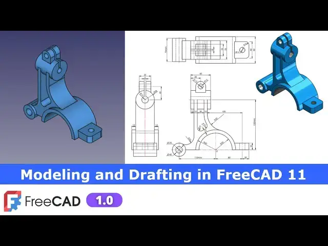
Modeling and Drafting in FreeCAD 11 | FreeCAD Tutorial | FreeCAD Drawing | Mechnexus |
Dec 31, 2024
#freecad #freecaddrawing #freecadpartdesign
In this video I have explained How to do Modeling and Drafting in FreeCAD.
▶️ Visit my website for more info on FreeCAD-:
https://mechnexus.com/
▶️ Get my FreeCAD Crash Course for beginner-:
https://www.udemy.com/course/freecad-course-for-beginner/?referralCode=3BA9B526A12F96295D44
▶️ Download Source File of Tutorial-:
https://mechnexus.com/mechnexus-youtube-tutorial-source-file/
▶️ Buy Me a Coffee
I am very grateful that you watch my videos and I am constantly trying to improve the quality of the videos on this channel. If you'd like to help me do this, please consider supporting me so that I can to continue to produce content for your enjoyment.
👉 Help support this channel by buying me a coffee: https://ko-fi.com/mechnexus
All donations will be used to purchase equipment to improve my productivity and increase the quality of the content that I produce. Your kind support will help to grow this channel. Even if it's just enough to buy me a coffee every little helps and this will be repaid in full through my sharing of knowledge.
Show More Show Less View Video Transcript
0:00
Hello friends welcome to fre tutorial and in this tutorial we will convert this orthographic uh drawing into the 3D
0:06
model and as you can see that I have already converted it and it is matching
0:12
with a isometric view of the drawing and in this tutorial we will not only create
0:19
this uh 3D model with the help of uh this orthographic view but also we will
0:26
create the drawing how we can create a detailing of any parts and if you see in
0:34
this drawing if we apply gdnt and uh tolerances so we can release this
0:40
drawing for the production but this tutorial is a designed for the user who
0:47
wants to learn modeling as well as detailing in a free can so I will close
0:53
this file and create a new file and we will start creating model from this View
0:59
and then we will create a drawing so let's start you can also visit my
1:05
website Mech nexus.com where I write articles and tutorials on freead you can
1:12
download my tutorial source file from here tutorial source file page and you
1:18
can also support me by buying a cup of coffee on kofi.com your uh small support
1:27
will help these channels to grow and it will motivate me to create more awesome content on fread I thanks to all my
1:36
supporter those who have a supported me by buying a cup of
1:41
coffee so keep supporting and uh it will help me to grow this Channel and it will
1:49
motivate me to create more awesome and useful tutorials on free cat so let's
1:55
come back to our tutorial so here I have a create cre a new file and I will uh switch to the
2:02
part design workbench and I will create my body and then select option to create a sketch
2:10
and we will select this front
2:18
plane now if we Zoom our drawing so we can see that uh inner radius is of a 50
2:25
and outer is a 60 so we will uh simply create a
2:30
3point Arc and uh make it a coincidence and we
2:38
will create one more three-point Arc and we will select this and this and
2:45
make it coincidence and now we will uh close our
2:56
profile and I will select this and this and add a horizontal
3:04
relation now we will provide the dimension so we will select radius inner one is of
3:12
50 and outer one is of
3:20
60 now I will move these
3:25
Dimensions our sket is fully constrain we will come out of it and we will will create a Extrusion of 80mm which we can
3:32
see here so select the sketch click on extrude and uh we will keep it symmetric
3:40
to the plane and provide the dimension
3:45
80mm click on okay
3:53
now if you see in a side view if you see in a side view there is
3:59
a distance given 12 mm which means that we will create a datm plane at a
4:04
distance of 12 mm from this pH so click on the data plane and in the Z Direction
4:10
I will provide the 12 mm and uh I wanted to reverse this
4:15
direction so I will provide here a negative symbol now I will click on okay now we
4:24
will create our sketch on this dat temp plane so we will select it and click on the sketch
4:30
and from here we will switch to the wireframe
4:35
view and let's uh hide this dat temp plane so first thing which we will do is
4:42
to project that outer radius click on
4:48
project and uh we will create a three-point
4:58
Arc and now we will rotate our model select this and this Arc and uh
5:05
made it equal and we will select this and this point Arc Center and click on the
5:13
coincidence now now uh we will create this profile
5:20
so for this first we will select a line tool and draw the horizontal
5:25
line and here we will create a three-point
5:33
Arc and select this and this and add a coincidence
5:40
relation and this is of a diameter 40 which means that radius will be 20 so
5:46
select a radius and give it a 20 mm now we want to fix the center points
5:54
so if you see here it is a given the 1 one0 so I I will select a horizontal
6:01
Dimension select this and this and give it
6:08
110 now there is a Ark of r25 so we will
6:16
select a three-point Arc and create an
6:24
arc and this is of r25 so we will select a radius and I give it
6:33
25 and we will move it
6:39
Center or there is a vertical line which will
6:45
be tangent to this Arc so first I will create a vertical line and add a
6:52
tangency
7:00
and now if you see here so we can see here
7:06
here a 10 mm 20 mm 10 mm means 40 mm so
7:11
we will uh draw a horizontal line and select
7:18
uh horizontal Dimension and provide the 40
7:24
mm and uh we will create one more vertical line here so select line tool
7:31
dra the vertical line and here is a given radius
7:36
R50 so we will again select a three-point Arc
7:42
and create an arc and let's uh add a tangency relation here and here
7:51
also we will add a
7:56
tangent now we will uh fix this vertical height from
8:04
this our origin so select a smart Dimension and vertical height is of
8:14
150 which we can see here from this a to this
8:21
axis now we will constrain this which is of
8:26
radius 50 click on okay okay and
8:37
now here if you see 110 and uh this radius is
8:45
unconstrained so we will select this and this and made it
8:51
equal and let's try to move it what is on constraint so
9:00
so now our sketch is still un constrain because we have not assigned
9:07
relation between this and this so we will select this and this and add
9:15
a vertical relation so if you see here this got fully constrained but this
9:23
Arc is not so if you move it
9:32
and here we can see that this line having no any relation so we will add a horizontal
9:40
relation and we can see that uh this Arc is a
9:48
unconstrained because we have not added a tangency here let's add the tangency
9:56
so this is fully constrained and now
10:01
here is UN constraint so we will select this point and this point and con so our
10:08
sketch is fully constrained now we will uh come out of
10:14
the sketch and we will switch to the flat
10:27
lines and we will select our sketch and if you see in a top view so this is the
10:36
56 of Extrusion length so click on the
10:41
plat reverse give it a
10:47
56 click on okay and now we will switch to the front
10:55
view and if we see our isometric view so there is a circular profile and if you
11:02
see in a top view or in a side view it uh it is a symetric with our mid plane
11:09
so we will switch to the isometric view on our origin plane and uh select
11:16
this uh exit plane and click on sketch and we will uh off this origin
11:25
plane and now all we have to do is a project dis
11:30
Arc click on the project geometry and we will create a circle equal to our
11:39
projection and now I will uh come out of the
11:44
sketch and it is of 70 mm so I will select the sketch click on
11:52
the pad here I will give the 70 mm and I will select a symmetric to the plane
12:00
click on okay now switch to the isometric
12:07
view now if you see our isometric view so here is a
12:13
cut and we can also see in this front view so we will create this cut we will
12:18
select the face and click on the sketch and for better sketching uh we
12:26
will switch to The wireframe View and uh we will project this vertical and
12:33
this horizontal edges click on Project geometry and
12:41
now I will create a rectangle and I will uh delete this
12:50
one and if you see here the width is a 20 mm is given so I will give it a 20
13:01
and select this and this I will give it a 10
13:10
mm and from here it is a 10 mm it is over defining so I will close
13:18
it now I will select this point and this
13:24
construction one and make it coincidence
13:30
and here here is a 10 mm which means that if
13:36
this radius is 50 then it will be the 60 so I will select a three-point
13:44
Arc and I will select this two and add a
13:50
tangency and uh here is a 10 mm is given which means that this radius is 60 so
13:56
this will be the 70 so I will select a three-point Arc
14:02
create one Arc here and let's uh add a tangency here
14:09
first and move this point and uh select a three-point
14:15
Arc select this and this and select this and this and add a
14:22
tangent and now I will uh move this and here I will extend this line
14:29
and connect these two points with the help of an arc so select this and
14:39
this add a tangency select this and this and add a
14:45
tangency and now here we will project this outer
14:51
diameter so click on the project geometry and
14:56
now select this point and this point point and add a coincidence and select a smart Dimension
15:05
and that should be the 70 this is the
15:13
r10 now select this and this and add equal
15:19
constraint and here we will uh project this Arc and we
15:27
will add this and this as a coincidence relation so our profile is fully
15:34
constrained we will come out of the sketch and now I will switch to the flat
15:41
lines select the sketch and uh click on exclude
15:47
cut and say it through all so here switching from Flat lines to wireframe
15:53
here is a keyboard shortcut is given you can also use this keyboard shortcut now
16:00
now now we will uh create this hole here so select the face and click
16:08
on the sketch and its detail is it is of diameter 20 so I will uh click on Project
16:16
geometry project the diameter click on the
16:21
circle and select smart Dimension and uh give it a diameter 20 click on close and
16:30
we will go to the whole tools and here I Define my drill size of a 20 and from
16:37
here I will say through all say
16:43
okay now we will U move to the next
16:48
feature the next feature is to create a
16:53
data plane at a symmetric so first we will create a cut
16:59
so we will remove the material at this portion and then we will add the material so I will simply select this
17:08
pH and click on the data plane and here in offset I will give the 10
17:15
mm as my offset distance so you can see that uh plane is
17:22
inserted click on okay now I will select this dat temp plane and click on the
17:27
sketch rotate my model and from here I will
17:32
switch to the wireframe and I will project this
17:40
age and here if you
17:45
see in a side view so this is of a
17:51
r28 so we will create a
17:57
circle and we we will select the
18:07
diameter 28 multiplied by 2 which is
18:15
56 and now I will uh select this and this and add a coincidence now select
18:22
this point and rotate it and select this construction one and add a coincidence C
18:28
close it hide the data plane switch to the flat
18:34
lines select the sketch click on extrude
18:40
Cut select symmetric to the plane save through all say
18:46
[Applause] okay now we will again select uh the
18:53
temp plan now we have created the cut now we will create the circular profile
19:00
on the same dat temp plane so we will select the sketch now click on the project
19:06
geometry and now we will rotate our model we will create a equal Circle as
19:11
per our construction so select the circle
19:17
and click on close now I will hide my dat temp plan select
19:23
the sketch click on extrude and here is a Extrusion is of a 60 mm so we will
19:30
select symmetric to the plane 60
19:38
mm and click on okay
19:44
now we will create a next feature which is this one so we will uh
19:51
on our data plane and use the same data plane to create our
19:57
sketch now now we will switch to the isometric View and first we will project
20:03
this diameter click on the project and uh project this diameter switch to the
20:09
right View and uh from here switch to the
20:14
wireframe and here we will uh see the details so here is a R20 is given so we
20:22
will simply create a three-point Arc
20:34
and we will select this and this and uh made it equal first and
20:40
now here it is 35 so I will select the symmetricity
20:46
constraint select this point this point and this uh
20:52
axis and now I will select the polyline tool and close my
21:03
profile and uh make this
21:10
horizontal and this is the 40 and this is R1 15 so 40 + 15 is of a 55 so from
21:19
Center to this top point is of a
21:24
55 and this horizontal one is of a 35 so give it
21:32
35 and add it vertical relation so our sketch is fully
21:38
constrained we will hide this stum plane and switch to the flat lines and now we
21:45
will create our Extrusion of a
21:53
[Applause]
22:09
our sketch is fully constrained and here we can see the radius is a R15 so we
22:16
will select it and click on extrude set it symmetric to the plane
22:22
and we will give it a 30 mm click on okay
22:29
now we will provide the fillet of R15 so I will select this two
22:37
ages and uh provide the fillet of
22:45
14.99 now we will create this hole of diameter
22:51
15 so select the ph and uh click on the sketch click on the project geomet
22:59
tree and uh create a circle and select
23:06
diameter give it a 15 mm click on close now go to the whole
23:13
Wizard and uh give it a 15 mm and from here say it through
23:19
all say okay now let's uh move to the next
23:26
feature which is to create this which we can see here in isometric view
23:31
so we will select this face and click on the sketch we will rotate our model to the
23:38
right orientation and now first thing we will do is to project this uh outer
23:44
diameter and from here we will switch to the
23:50
wireframe and uh I will create a
23:57
circle now I will create a
24:05
rectangle and I will use the trim tool select the trim trim
24:15
it and this and uh this is of a diameter 15 if you see in a side
24:24
view sorry this is a diameter of r10
24:29
so we will do the diameter of a 20
24:35
mm and as we wanted to remove the material
24:40
so this height is not constrain for us so we will
24:47
give let's give the 60 mm so that this
24:53
should become come outside of the body and I will make this and this
24:58
symmetric so here I will use the symmetricity constraint select this point this point and this
25:05
axis and I will select the horizontal Dimension and if you see in a side view
25:12
here is a 5mm is
25:18
given click on Okay now click on close we will uh switch to the flat
25:24
lines and select the sketch click click on extrude
25:30
Cut and from here I will say it
25:37
all now if you see our model so we have made this feature this one and this one
25:44
now we will create here this uh face so this is on a mid plane so we
25:51
will on our mid plane and we will select this exit plane and click on the sketch
25:59
now I will off my origin plane and I will project this outer radius click on Project
26:06
geometry and let's switch to the wireframe and
26:13
here height is given is of 20 mm so we will uh create a three-point
26:23
Arc and uh I will select this and this and uh made
26:31
it equal and I will select a polyline
26:36
tool and draw the approximate
26:45
profile now
27:00
select line tool now the height is given is 20 so we
27:08
will select a smart Dimension and provide the 20
27:13
mm and uh this is the horizontal and if you see here so this
27:21
is given 50 so which will be us in Extrusion and from the center it is a
27:29
880+ 2000 so we will select a smart Dimension
27:34
select this point and this point and at 100
27:41
mm now I will uh close it switch to the flat
27:48
lines and now we will extrude it to the distance of a 50 select the sketch click on exclude
27:58
and we will give it a 50 mm and never forget to make it symmetric to the plane
28:04
and click on [Applause] okay now we will create this hole so we will
28:12
select the stop face and uh click on the sketch rotate our model to the right
28:22
orientation and we will click on the circle and create a circle so position
28:28
of this hole is the 0 so we will switch to the wireframe so that we can get a
28:35
origin Point select this and this and provide
28:41
0mm and uh this whole Dia is of 16 so give the 16 click on
28:51
okay now select the sketch go to the whole Wizard and uh drill size of
29:00
16 and simply say through all say
29:05
okay now we will provide the fillet of
29:11
r10 to this two edges which we can see here in isometric
29:18
view select it and provide the 10 mm click on
29:25
okay now we will switch our model to the isometric
29:31
view so you can see that we have successfully converted this autographic drawing into the 3D
29:38
models now we will apply the color which will match to the isometric view so
29:44
select the last feature go to the appearences and go to the custom appearences
29:51
and uh
29:58
Let's uh give the approximate color so this is how we have a
30:07
successfully created a model and also apply the color now we will also create
30:13
a drawing offit with respect to the front top and side view so I will close
30:19
this file by saving it let's uh
30:28
let's I will give it a revision
30:39
R1 now
30:57
[Applause]
31:06
now we will uh create a 2d drawing of it so I will switch to the tech draw
31:15
workbench and in a track draw workbench first I will insert my template click on the template and here
31:22
I will use A3 landscape minimal
31:30
and I will go to the my model tab so this is our base
31:36
view so select the base feature and
31:41
click on insert view now here we will set
31:49
the scale type page and here I want right side of
31:56
view so here it is a first angle of projection but our drawing is at a third
32:02
angle of projection because we are seeing this uh circular
32:10
profile line visible and this this feature is in a hidden so this is a
32:16
third angle of projection so I will switch here to the third angle and
32:25
now I will place my top f so once the views are the
32:32
place we will set to okay and now we
32:37
will change our scale so our scale is of the pace type so here let's do 6
32:50
scale and click on rebuil if uh view is not updating
32:58
then save it if it is still not updating then expand it go to the projection view
33:06
and say okay again so it will recalculate it
33:13
now I will move my side view and my front
33:23
view now once the view position is
33:28
okay I will lock the view position I will lock this uh side view and I will
33:33
also lock this top view and now we will uh insert the dimension so let's start
33:40
with the front view so here we have to on the hidden line if
33:46
you want to give these Dimensions so select the base View and go to the
33:51
options here here is a hard hidden is a false set it true
33:58
so you can see that now hidden line is on so first thing which we will do is
34:06
to enter the center line select this and this and add a center line and now let's
34:15
give the dimension select this Center points and this and uh provide the horizontal
34:22
dimension of at now from this to this C point
34:28
select and provide the horizontal dimension of a 20 mm and select this
34:33
point and this point and add a vertical dimension of 20
34:40
mm and uh this radius is of R50 and outer one is a 60 so select it and go
34:48
here and select the radius Dimension R50 and select the outer one and uh give
34:57
it to
35:04
r60 and now here is a 10 mm is given so this will become the
35:12
r70 so I will select this one and go here and select the
35:18
radius and move
35:23
it now from this Center to this
35:30
Center give the horizontal Dimension which is of
35:38
110 Let's uh move it little bit
35:54
down now we will provide this diameter diameter 20 and 40 so we will select the
36:02
inner diameter go to the diameter this is off for
36:09
20 select this and provide the diameter
36:17
40 and this is of r25 so select it and provide r25
36:28
and now provide this two radius r10 r10 so select
36:35
this and provide it R 10 here and select this and provide it R
36:46
10 move it now we will provide this 150 Dimension
36:53
so for this we have to insert a center line so we will select this and this and uh
37:04
add a center line between two lines click on okay and
37:10
now we will select this cot point and this Cod point I can also select a line
37:18
but this Cod point is on this axis so I will select a vertical
37:23
Dimension and provide the dimension of 150 now from this axis to this one is a
37:33
105 so I will uh select this Cod
37:38
point and this uh AIS and select the horizontal
37:46
Dimension so here is uh it is
37:52
coming 105 but here is coming 125
37:58
so if you see here 2080 and 110 it is a
38:03
matching mean this is a fix and here it is
38:10
R50 so let's check it select
38:17
it first select the radius and so this is the
38:24
R50 but here it is given 105 so we will
38:30
go in our model and we will correct it so this is the
38:42
pad and we will uh select the sketch so
38:50
here it is a 80 mm and from here it is given
38:56
105 so so what we will do we will uh create a
39:01
line and make it a [Applause]
39:09
construction and we will select a horizontal Dimension select this and this and
39:19
provide it atmm
39:29
and now if you see here it is a 11 1
39:35
0 and it having the vertical relation here so what we will
39:42
do we will delete this vertical
39:50
relation and now see
39:57
now from this to this we will provide
40:04
105 so select smart Dimension select this and
40:10
this and provide it
40:19
one5 so it is a calculating so this is how we have found
40:26
the mistakes in our modeling and we have corrected it now I will come out of the
40:32
sketch and I will on the one feature one by one to check it if there is any
40:38
failure in the model okay now I will hide this dat temp
40:47
plane and I will save it and go to the my drawing view so here some of the
40:55
things got Disturbed
41:03
now we will fix the dimension which got Disturbed due to the model changes so I
41:09
will delete it and here I will again insert the
41:16
center lines and click on okay
41:28
and here I will uh also delete this
41:33
Dimension delete this and delete
41:41
this and now I will move my Dimensions to the right
41:48
positions and now we will select this
41:54
axis this axis and this this C Point our required Dimension is a
42:02
105 so now it is perfect so you can see that free CAD is a parametric once we
42:09
have modified the models our drawing is also
42:14
changed now I will select this and this and uh
42:21
provide the horizontal dimension of uh 80 mm and uh I will select this axis and
42:29
this Cod point and provide the horizontal dimension of uh 20
42:36
mm and now let's uh provide the dimensions
42:44
here this uh 10 10 20 and 10 so we will
42:49
uh select this and this provide the horizontal dimension of
42:55
10 mm select this and
43:01
this select the horizontal dimension of 10
43:06
mm select this and this provide the horizontal dimension of uh 20
43:16
mm and select this and this provide the horizontal dimension of 10 mm
43:29
now we will provide this Dimension so we will select this Cod
43:35
point and this Cod point and provide the horizontal dimension of
43:42
60 select uh this and uh provide the radius of
43:48
R15 Let's uh move it so here we have given the radius of
43:54
14.99 because if I give the round figure it fails so here I will go to the
44:00
Precision option and uh decrease the decimal presses and we will select this
44:05
diameter and add a diameter Dimensions which is of 15 mm and select
44:14
this cord point and this Center points and add a horizontal dimension of 30 mm
44:21
and here I will decrease the Precision
44:29
now here I will uh unlock my top
44:34
view and move it little bit upper side
44:39
and again I lock it so if you see our front view we have
44:44
given all the dimensions and now let's uh move to the
44:50
side view
45:00
now if you see in a side view there are the two Dimensions 12 mm 12 mm
45:07
now I will select these two Cod points and select the horizontal
45:13
dimension of a 12 mm select this and
45:19
this at a 12 mm and now here I will on the hidden line so I will
45:27
select this View and here hard hidden is a
45:33
false set it true and now you can see that uh hidden
45:38
line is on and now I will insert a center line
45:46
but this Cod Point as a center so I will select this and
45:51
this this Center and this C point and
45:57
add a vertical dimension of 40 and here I will decrease the decimal
46:04
place to make it round of 40 and here it is of r28 so I will select the
46:13
radius and give it to
46:18
r28 and now this cut is of a 5mm so I
46:23
will select this and this and and uh add a horizontal dimension of a 5
46:31
mm and move it and select this and this and add a
46:40
horizontal dimension of
46:46
35 so you can see that we have all given all the dimension of a side view and
46:52
let's move to the top view
47:01
now here we will also on the Hidden View so hard hidden is a
47:07
false set it true so that we get a hidden lines select this
47:14
point select this point and add a vertical dimension of
47:22
70 and this is of a 5 mm select this and this and add a
47:29
vertical dimension of a 5 mm select this
47:35
line and add a vertical dimension of 56 and select this and this and add a
47:44
vertical dimension of a
47:50
35 now we will provide this uh 60 mm
47:55
dimension how much it is let's uh Zoom it so this
48:02
is the 80 and we will select these two Cod points and add a vertical
48:09
dimension of 80 mm select this
48:14
diameter give the diameter dimension of uh 16 and this is of
48:25
r10 give it a r10 and
48:33
this width is of 50 mm so I will
48:38
select if you are facing problem in a selection then Zoom it and select the
48:44
cord point and give it a dimension
48:51
50 so if you see we have given all the dimension in a
48:57
top view front view and side view now we will off the frame and we will
49:05
now insert the center marks so I will select this radius and set the center
49:12
marks select this and add a center marks and select this and add a center
49:22
marks and now in a side view we will insert a center Mark select this and uh
49:29
add a center marks and here we will select this age and this
49:38
age and add a Center
49:46
Line similarly here we will select this and this age because these are the
49:52
longest age and we will add a center line
49:58
click on okay now we will also add one Center Line
50:06
here select this and
50:15
this click on okay and we can do few things like uh
50:22
this 5mm Dimension we can add a equal symbol so that it is a symmetric with
50:28
the center lines we can do the same thing with the
50:33
70 mm Dimension add the equal symbol so that
50:38
uh it is a symmetric with the center line but we have not drawn the center
50:43
line so we will select this H and this
50:48
H and we will add a Center Line click on okay similarly we will
50:56
select select this ede and this Ed and add a Center
51:01
Line click on okay
51:07
similarly we will select this and add a center Mark and we can also add a center
51:15
line so that our drawings looks good okay
51:22
now this two Dimension we can also add a symmetry it so that these are the
51:28
symmetric with the center line and this 35 as
51:35
well even though these details are not given here that is my
51:42
understanding and this 5 mm we can also add equal symbol and this uh 50 mm as well
51:57
now let's move it and now we have successfully given the
52:04
dimension with respect to the orthographic View and now we will insert this uh isometric view so we will go to
52:11
the model tab we will switch to the fitall and set our model to the
52:18
isometric and we have selected our body here make
52:26
sure your body should be active and click on here insert active View and
52:33
from here click on the crop image so that we get options to customize the
52:38
border of our this view click on okay and now switch to the drawing view so
52:44
you can see that this uh isometric view is placed but we have to on the frame if you
52:52
wanted to move our active view so here we can see that uh the border is larger
52:58
than our view so we will go to the its property so here let's uh make it a
53:07
90 by 90 and let's increase the scale let's
53:15
make it 1.4 and now we will make
53:22
it0 and 110 let's see little more we want to increase in
53:28
height let's say 120 so you can see that now it is a
53:35
perfectly placed now we will off the
53:44
border and I will move my drawing to the correct
53:53
position so this is how we we have successfully model this part and I have
54:01
we have also created the 2D drawing you can apply the gdnt to this part and
54:07
other technical details you can on the frame and you can edit the title block
54:13
field like it is a free card modeling and drafting let's I edit the
54:19
title modeling and drafting in freead click on okay this is not an assembly
54:25
drawing this is part drawing so I will make it
54:31
part and here I enter my
54:37
name created by me and uh approv by me
54:43
so let's see the okay so this is how you modify the title
54:49
Fields so this is all about this tutorial how to create a model and also
54:57
create a drawing in freeat this is modeling and drafting tutorial in
55:02
freecat thank you for watching and thank you for your valuable time
#CAD & CAM
#Jobs & Education
#Education
#Sculpture