live_tv
Livestream Starting Soon
00
Hours
:
00
Minutes
:
00
Seconds
Up next in 10

Model Stud Guide with FreeCAD Part Design Workbench | FreeCAD Tutorial | 3D Modeling |
May 16, 2025
#freecad #freecadtutorial #learnFreeAD
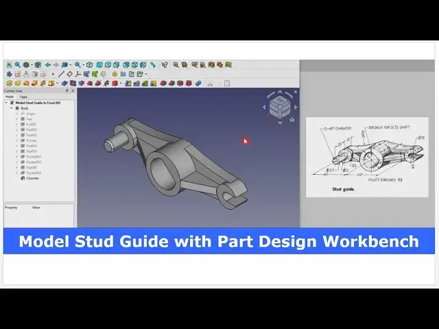
In this video I have explained How to Model Stud Guide with FreeCAD Part Design Workbench.
▶️ Get my Complete FreeCAD Course : From Zero to Expert !
https://ko-fi.com/s/1ab4385434
▶️ Join my channel membership and keep supporting my work:
https://www.youtube.com/channel/UCcn6z2whMaFu-_LDsEXCfVA/join
▶️ Visit my website for more info on FreeCAD-:
https://mechnexus.com/
▶️ Download Source File of Tutorial-:
https://mechnexus.com/mechnexus-youtube-tutorial-source-file/
▶️ Buy Me a Coffee
I am very grateful that you watch my videos and I am constantly trying to improve the quality of the videos on this channel. If you'd like to help me do this, please consider supporting me so that I can to continue to produce content for your enjoyment.
👉 Help support this channel by buying me a coffee: https://ko-fi.com/mechnexus
Show More Show Less View Video Transcript
0:00
friends welcome to Frecad tutorial And
0:02
in this tutorial we will model this stud
0:04
guide in Frecad As you can see that I
0:07
have already modeled it and I will show
0:10
you from the scratch how you can do the
0:12
same in
0:13
Frecad So I will close this file and
0:16
create a new
0:18
file If you want to learn free CAD from
0:21
the scratch then you can buy my complete
0:24
free CAD course from zero to expert This
0:27
course also available on Udemy but uh
0:31
problem is that uh UDMI only give me the
0:35
37% of a core selling You can see here
0:38
user had paid $15 but I have only got $5
0:45
If you wanted to see the review of my
0:48
course you can go to the Udemy and s
0:51
search for the free CAD and you will see
0:54
my course complete free CAD course from
0:57
zero to expert and this course is took
1:00
by the more than 2,000 students and I
1:04
have got the rating of a
1:06
4.1 for the demo lectures you can expand
1:10
it and uh see the demo lectures and the
1:14
course structure But I will request you
1:18
if you found my course interesting and
1:22
uh reviews of the other student on Udemy
1:26
then I would request you to buy my
1:30
course from the my coffee shops because
1:34
if you buy from here it will help me a
1:37
lot
1:39
So once you buy my course you will be
1:42
redirected to the Google drive and here
1:44
is the my course complete free course
1:48
from zero to expert Go inside and uh the
1:53
sections I have shown you on my Kofi
1:57
shop page So exactly same lectures under
2:02
the section is created For example
2:06
section one is a introductions to free
2:09
1.0 and what is new in a freecad 1.0 So
2:13
if you go to the section one so there
2:16
are the 18 lectures and if you go inside
2:19
of the sections one you will find the 18
2:23
lecture total And once you go to the
2:26
lecture one you will find a video file
2:29
which you can download to your system
2:32
and you can watch it And uh this course
2:36
is uh updated on a equal interval of a
2:39
time once the new feature since came And
2:42
uh once you purchase the course you have
2:45
the lifetime access to the course and in
2:49
the case of any doubt any query you can
2:52
mail me at admin
2:55
rate.com You can find my course link on
2:59
my YouTube channel You can see the
3:02
course link and uh you can also find my
3:05
Kofi course page link on uh pin comments
3:09
and uh video descriptions
3:14
So here I have created a new file and I
3:16
will create a new body and I will on my
3:18
origin plane and I will select this
3:22
front plane for create my base sketch
3:27
because if we look the model from this
3:30
side then it would be better to create
3:33
this base profile and then create these
3:36
two bosses and rip and this middle round
3:40
profile So I will go to the model press
3:42
the space bar and hide the my planes
3:48
Now I will create the three
3:58
circles and these
4:01
two distance is a 65 from the center
4:06
So we will select these two
4:09
points and give it
4:13
65 Select this point and this
4:18
point and give the
4:23
65 Now this uh middle one is of diameter
4:27
44 So we will select it and give it
4:32
44 And this one is a 25
4:37
And this one is also
4:41
25 Here 25 And this one 25
4:47
Now we will connect this three circle
4:50
with the help of a
4:53
arc So we will select the threepoint
5:01
arc and create the arc Similarly
5:06
here here and at the
5:15
bottom
5:18
Now we can see that here is a
5:22
coincidence constraint but no
5:24
tangency So I will apply the tangency
5:27
with this and this Apply
5:31
tangent Similarly here apply
5:34
tangent at
5:37
bottom
5:39
tangent and
5:42
tangent
5:45
Now I will apply the vertical relation
5:55
Similarly
5:57
here
6:02
vertical
6:04
vertical Now let's see what is done
6:14
constraint So here we will find the
6:18
conflict We'll delete it
6:23
So here if you look at here we have not
6:26
applied the tangency So we will apply
6:29
here
6:31
tangent and this one
6:36
tangent Select this and this apply
6:40
tangent and this and this apply
6:44
tangent So we have a fully constrained
6:46
profile Now the middle circle we will
6:49
keep in a
6:51
construction and we will select the
6:53
threepoint
6:55
arc and create an
7:04
arc So we have fully constrained profile
7:08
and
7:09
now we will use trim tool to trim it
7:18
We'll close
7:19
it and I will give the
7:23
extrusion length of a 10
7:25
mm Click on
7:28
okay And
7:30
now we will create these two
7:33
bosses So we will select the face Click
7:36
on the
7:37
sketch Click on the project geometry
7:40
Project this age and this edge
7:43
Click on the
7:46
circle Create the two
7:51
circles Now close
7:55
it And this both are of the 15 mm So 10
7:59
mm extrusion we have given So we will
8:02
give the 5 mm Click on the
8:07
pad Click on okay
8:11
And
8:13
now we will create this cut So we will
8:16
select this face and click on the
8:19
sketch And now I will click on project
8:25
geometry And
8:27
now I will
8:30
uh create a slot
8:41
And we will delete
8:44
it And select this point and this arc
8:48
Make it coincidence This point and arc
8:52
Make it
8:53
coincidence And we will make it
8:57
horizontal Make it
9:00
horizontal And this slots width is a 9.5
9:04
So I will select these two points and
9:08
give it
9:11
9.5 And now select the threepoint
9:18
arc Now close
9:21
it Now we will select the pocket
9:25
tool and we will say it through
9:28
all Say okay Now if you see that these
9:32
two bosses which we have made is not
9:35
merged with our base
9:39
feature
9:41
So we will refine it to go to the data
9:45
tab and here is a part design refine
9:49
false set it true So you can see that it
9:53
has been merged
9:55
Now we will create this center
9:58
boss which is a round feature of
10:02
diameter 44 So we will select the face
10:05
click on the
10:06
sketch and we will project the arc Click
10:10
on the
10:15
circle Click on
10:18
close And this is of the 20 mm So click
10:22
on the
10:24
pad and give it 20
10:28
mm Click on
10:31
okay And now we will also merge
10:34
it Refine false Set it
10:39
true So it is has been perfectly merged
10:42
Now we will create this BR for
10:47
31.75 shaft So you will select the face
10:51
and click on the
10:54
sketch click on the
10:59
circle select
11:01
diameter and give
11:07
31.75 Click on
11:09
okay But now
11:12
here we have to provide a cut So we will
11:18
again go to the
11:21
sketch So this is the profile of a shaft
11:25
Shaft having the cut So for this we will
11:28
select a
11:29
line and create a line and we will
11:33
concide this line with our
11:36
origin And now we will click on the
11:40
angle and give the angle 45
11:45
And this one we will make as a
11:48
construction Now select the
11:50
line We will create one more
11:53
line and we will make it
11:57
parallel Now we will create one more
12:03
line and we will make it
12:07
construction So
12:09
this distance is not given
12:14
Therefore we will take the approximate
12:16
distance of 10
12:27
mm And now we will trim this one So
12:31
click on the trim and trim it Click on
12:35
the close
12:37
as backside face is not visible but we
12:40
can assume that uh this shaft will go
12:42
through this part So we will select the
12:46
sketch click on the
12:49
pocket and we will see it through all
12:52
say
12:55
okay and
12:59
now we
13:01
will add this boss here So select the
13:04
face Click on the
13:06
sketch Click on project geometry Project
13:09
the
13:11
diameter And this round is
13:15
of diameter 12.7 So select the
13:20
circle Click on the diameter and give it
13:23
uh
13:25
12.7 Click on close And this extrusion
13:29
length is of 20 mm So click on the
13:33
pad and give the 20
13:40
mm
13:42
isometric And now here is a chamfer of
13:45
1.5 to 45 So we will click on the
13:49
chamfer Select the age and give the
13:52
chamfer value
13:55
1.5 Click on okay And
13:59
now we will create these two ribs So for
14:04
this we will select this face and click
14:07
on the
14:08
sketch and I will project this
14:12
diameter and this rib of 8 mm thickness
14:16
on the both the side
14:20
So I will also project this
14:26
diameter And
14:28
now I will draw the two horizontal line
14:31
one as the top and other as a
14:34
bottom And now I will use the
14:37
symmetricity
14:38
constraint Select this point this point
14:41
and this
14:43
axis And now I will uh select the
14:47
threepoint
14:48
arc and create a
14:52
arc Similarly
15:07
here we will switch to the wireframe
15:19
So first thing we will provide the
15:23
dimension of 8 mm
15:28
thickness and I will select this arc and
15:31
this arc and make it
15:34
equal Now we will close it
15:39
Switch to the shaded
15:41
view by pressing the
15:45
V7 at the same time V key and seven And
15:49
now select the sketch Click on the
15:53
pad and I will reverse the
15:56
direction And here I provide the end
15:59
condition up to face and select this
16:02
face Click on okay
16:05
And
16:07
now I will provide the cut So I will
16:11
select this face and click on the
16:15
sketch And now here I will project these
16:18
two
16:22
geometry this one
16:26
and this one And at the same time I will
16:30
switch to the wireframe and switch to
16:32
the top view Now here I will select the
16:35
line
16:36
tool and connect these
16:39
two And I will also project these two
16:45
lines and I will complete my
16:53
triangle Now I will close
16:58
it
17:02
Now if we go to the shaded view here you
17:07
can see the all the keyboard shortcut
17:10
here Now I will select the sketch click
17:13
on the
17:16
cut and I will say it through
17:22
all Click on okay
17:26
Now due to
17:29
cut here my boss material also got
17:33
removed So we will add the material So
17:36
we will select the face and click on the
17:39
sketch Click on the project
17:43
geometry Project the outer diameter Now
17:46
select the threepoint
17:50
arc and make this and this
17:54
equal and now click on the
18:00
line and complete the profile Click on
18:04
close Click on the
18:07
pad Click on the
18:09
reverse And now here I will select up to
18:14
face condition and I will select this
18:16
face Click on
18:19
okay But here we can see that solid is
18:22
not merging So we will set refine
18:33
true So you can see that uh everything
18:36
is
18:38
merged And now we will create one more
18:42
rip on this
18:44
side For this we will again select this
18:47
face and click on the
18:51
sketch and we will click on project
18:59
geometry and I will draw the two lines
19:13
And I will make it
19:22
horizontal And now I will make it
19:24
symmetric as we did for our previous
19:26
case Select this point and this
19:30
axis Select the threepoint arc
19:43
And here I will add the coincidence
19:48
relation Switch to the wireframe
19:57
Now I will select the
20:00
dimension and provide the thickness of 8
20:05
mm and this
20:08
arc This and this I will make it
20:13
equal Click on
20:18
close And now I will click on the pad
20:24
Click on
20:26
reverse Click on the up to face and
20:29
select this bottom
20:30
face and click on
20:35
okay And
20:37
now I will select this face and click on
20:41
the
20:42
sketch Switch to the isometric
20:46
view Click on project geometry
20:58
And from here we will switch to the
21:02
wireframe And we will also project this
21:06
one This one and this one Now we will
21:10
select the line tool and complete our
21:13
triangle for material removal
21:23
on
21:27
close Now click on pocket
21:31
tool and from here say true
21:35
all Click on
21:38
okay Now we will select our last feature
21:42
and click on refine tool
21:45
So you can see that uh it is perfectly
21:48
merging here as
21:50
well and this rib
21:54
also click on
21:56
isometric So this is how we have modeled
22:00
this stud guide and here is a common
22:02
node fillet and round R3 So provide the
22:05
fillet to the part and uh if I provide
22:09
the fillet then video will be too long
22:12
So this is how we have completed our
22:15
stud guide model and we have redid
22:18
drawing carefully and we have did it So
22:22
this is all about how to model the stud
22:24
guide in frecad with the help of a part
22:27
design workbench Thank you for watching
22:29
and thank you for your valuable
22:35
time
22:36
[Music]
22:57
Heat
23:01
Heat Heat
23:05
[Music]
23:12
[Applause]
23:22
Heat
23:28
[Music]
23:38
Heat Heat
23:42
[Music]
#CAD & CAM