live_tv
Livestream Starting Soon
00
Hours
:
00
Minutes
:
00
Seconds
Up next in 10

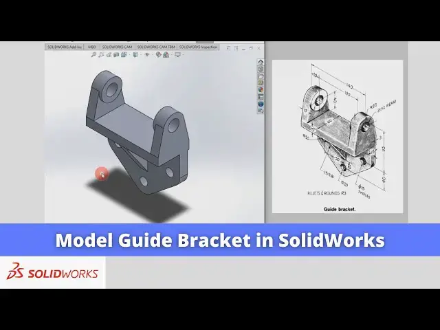
Model Guide Bracket in SolidWorks | SolidWorks Tutorial | SolidWorks Modeling |
Apr 24, 2025
#SolidWorks #solidworksmodeling #solidworkstutorial
In this video I have explained How to Model Guide Bracket in SolidWorks.
▶️ Download This Tutorial Source File From my Ko-Fi Store-:
https://ko-fi.com/s/d8a110f255
▶️ Visit my website for more info-:
https://mechnexus.com/
▶️ The Complete SolidWorks Course : From Zero to Expert!-:
https://www.udemy.com/course/solidworks-complete-course-zero-to-expert/?referralCode=B30458218EA1375DDB6E
▶️ Buy Me a Coffee
I am very grateful that you watch my videos and I am constantly trying to improve the quality of the videos on this channel. If you'd like to help me do this, please consider supporting me so that I can to continue to produce content for your enjoyment.
👉 Help support this channel by buying me a coffee: https://ko-fi.com/mechnexus
👉 Indian User can Support My Work Using my UPI ID: amar.patel456@ybl & amar.patel456@axl
All donations will be used to purchase equipment to improve my productivity and increase the quality of the content that I produce. Your kind support will help to grow this channel. Even if it's just enough to buy me a coffee every little helps and this will be repaid in full through my sharing of knowledge.
Show More Show Less View Video Transcript
0:00
Hello friends welcome to Solid Works
0:02
tutorial and in this tutorial we will
0:04
model this guide bracket in a solid
0:06
works here we have a isometric View and
0:10
we will read the dimensions and we will
0:12
create its model in solid works you can
0:16
also visit my website macn nexus.com and
0:20
you can visit this solid works tutorial
0:23
tab where I have written so many
0:27
tutorials on solid works where you can
0:30
follow the step byst step guide to model
0:33
the
0:34
parts if you like my method of teaching
0:37
then you can also support me on kofi.com
0:40
you can buy me a cup of coffee your
0:44
small support will help these channels
0:46
to grow and it will motivate me to
0:49
create more awesome content on solid
0:51
works so let's come back to our tutorial
0:56
so here I will select this front plane
0:59
and create create a sketch and first we
1:02
will create this base
1:04
profile for this I will select a twoo
1:07
rectangle and draw a
1:10
rectangle and now I will select this
1:12
bottom line and this origin point and
1:14
add the coincidence
1:17
constraint and we can see that total
1:19
length is a 140 so we will select the
1:22
bottom line and we will give its
1:25
dimension for this I will select this
1:27
smart
1:28
Dimension and give the dimension of
1:33
140 and now we will select this line and
1:37
our origin
1:39
point and we will link this Dimension
1:41
with our overall length for this we will
1:44
press the equal symbol click on one on
1:47
our 140 Dimension and divide by two
1:52
click on okay so now we have link this
1:56
Dimension that's why we are seeing the
1:58
sigma symbol
2:00
and
2:02
now we will give the total height for
2:05
this we will select the smart
2:09
Dimension and here we will directly add
2:12
the values so first one is a 15 mm which
2:15
is a
2:16
thickness
2:18
plus 40
2:21
mm
2:24
plus 20
2:26
mm so this is 75 15
2:30
+ 20 +
2:32
40 and
2:36
now thickness is 15 mm so we will select
2:39
the line
2:43
tool draw the rough profile and then we
2:49
will select this uh trim entities and we
2:51
will click on
2:54
close trim to closest and we will trim
2:58
this one and now
3:00
we will give the thickness dimension for
3:03
this we will select the smart
3:08
Dimension and give it 15
3:12
mm we will select this line and give the
3:17
dimension and we will press the equal
3:19
symbol and Link with this Dimension say
3:23
Okay similarly
3:27
bottom it is also 15 so so we will press
3:30
the equal
3:31
[Music]
3:33
symbol and Link the
3:35
dimensions so advantages of a linking
3:38
Dimension is if you change this
3:40
Dimension these two Dimension will
3:42
automatically get
3:44
modified now we will come out of the
3:49
sketch and our total Extrusion length is
3:52
a 60 we will press crl + 7 to switch to
3:56
the isometric view we will select our
3:59
sketch
4:00
click on
4:03
extrude we will give the
4:05
60 and from here we will select the mid
4:09
plane we will say
4:12
okay
4:15
now we can see that this is the radius
4:21
R20 so for this we will select all these
4:25
four edges
4:30
and click on the
4:33
fillet and from here we will click on
4:37
the full
4:39
preview and we will give the 20 mm
4:58
radius now
5:01
we will remove the material for this we
5:05
will select this face and click on the
5:08
create sketch we will select the circle
5:12
we will draw a
5:17
circle now we will move
5:19
it and we will select this circle and
5:23
this Edge and add the tangent
5:27
relation and uh this
5:30
is a R20 this means that this diameter
5:33
would be 40 so we will select the smart
5:37
Dimension and give it a dimension of
5:45
40
5:50
now we will select this right face and
5:55
we will select our origin point and this
5:58
diameter
6:01
and we will add the
6:03
relation
6:06
vertical now we will again switch to the
6:08
isometric
6:12
View and
6:15
now we will draw a line which will join
6:19
this one so we will select the line
6:23
tool we will create a line and
6:27
now we will add the tangent
6:35
relation tangent and we will click on
6:39
the trim trim to
6:41
closest and we will delete
6:45
it
6:46
similar process we will do on the other
6:50
site so we will select a
6:53
line or we can make this normal
7:00
so we will select this one and draw a
7:06
line now we will select this one and
7:10
this one and add the tangent
7:15
relation and
7:20
now we will select this one and this one
7:24
and add the coincidence relation
7:30
and
7:31
now we will trim this
7:37
geometry and we will close the
7:41
profile select the line
7:58
tool select this point and this
8:02
point and say
8:04
merge now we will come out of the
8:09
sketch we will go with extrude
8:14
cut here we will select this two
8:17
profile and we will say through all on
8:21
the both the
8:23
side click on
8:26
okay so now we have created this
8:30
profile press control 7 for
8:34
isometric now we will add this
8:37
boss for this we will select this pH and
8:41
create a
8:42
sketch we will select this uh Outer Edge
8:45
and click on convert
8:48
geometry we will select it and make it
8:53
construction and now we will select the
8:56
circle
8:57
icon create a
9:00
circle now we will come out of the
9:05
sketch so here we can see that 15 mm and
9:09
it is a 20 which means that this boss is
9:12
of 5 mm so we will click on extrude
9:17
boss and we will give the distance 5
9:20
mm click on
9:24
okay and now we will select this extrude
9:28
boss
9:29
go to the linear pattern click on the
9:32
mirror and we will expand our browser
9:36
tree and we will select this right
9:39
plane click on
9:42
okay
9:44
now we will create this whole feature
9:47
later let's create the bottom solid
9:52
phas now we will select the backside
9:54
face and uh right click and click on the
9:59
scale
10:00
H and
10:02
now we will make this phas
10:08
normal and now we will uh convert this
10:13
bottom age click on the convert
10:16
entities and
10:18
now we will uh create very rough
10:26
profile click on the line tool
10:41
now make this point and origin point and
10:45
add a vertical
10:47
relation now we can see that uh here is
10:51
a radius R20 is given which means that
10:55
uh this all three radius of R20 so we we
10:59
will click on the
11:01
fillet we will give the radius R20 and
11:05
add the three fillets here here
11:09
and here and say
11:14
okay now we will the give the
11:18
dimensions so we can see that from
11:21
Center it is a
11:24
95 and uh from this hole to this hole is
11:28
a 40
11:30
so for this we will uh project this
11:34
Ag and we will make it
11:39
construction and we will select a point
11:42
and insert a
11:47
midpoint and now we will select this
11:49
point and this Arc point and add a
11:53
dimension of
11:56
95 so for this we will select the smart
12:02
Dimension and add the dimension of
12:11
95 now this and this will have
12:17
horizontal
12:20
relation and from this Center to this
12:23
Center is 40 so I will select smart
12:27
Dimension and
12:29
give the dimension of 40
12:39
mm so our uh profile is fully
12:43
constrained we will come out of the
12:48
sketch now here we have the 3mm of set
12:54
distance so we will select our sketch
12:57
click on the extrude boss
13:01
and from here from we will select the
13:05
offset and we will give our offset
13:07
distance 3
13:09
mm now we will see that uh this offset
13:13
is going outside of the body so we will
13:16
click on this Arrow to flip its
13:21
direction and we will also flip this
13:26
direction so now you can see see that
13:34
uh it is a 3mm offset from the face and
13:39
thickness is a 15 so we will give here
13:42
the 15
13:44
mm and we will click on
13:48
okay so you can see that we have made
13:51
this bottom features and now we will uh
13:55
create a rib here so this is a 15 mm rib
14:01
rib for
14:03
this we will create this hole and we
14:06
will create this rib at the end so for
14:10
this we will uh select this face and uh
14:15
click on the sketch as it is a very
14:18
simple hole so we
14:21
will use the cut features or you can use
14:24
the whole feature that is up to you if
14:26
you want to use the whole features then
14:29
I can show you from the whole features
14:31
so let's go with the whole features and
14:35
uh let's see how we can do it so for
14:38
this click on the whole
14:44
Wizard and here we will select the
14:48
drill click on the
14:50
position select the
14:52
face and once
14:55
you click on the Outer Edge it send
14:59
Center get
15:01
snapped get highlighted so click on the
15:04
center now go to the whole type and here
15:08
if we go in a drill
15:11
size so we have this type of uh
15:16
drill we will go with a metric and let's
15:22
see drill is a
15:25
2.42 so here we do not have a drill
15:30
of that size so we will go with a custom
15:34
sizing and in a custom sizing we will
15:38
give our uh drill size 21.42%
15:59
you can create this type of a hole with
16:03
the cut features because most of the
16:06
time we do not get the drill size
16:10
recommended drill size by solid
16:15
works so but that is
16:17
okay
16:20
now we will create these three
16:25
holes which is of Dia 15
16:30
so we will select this face and uh click
16:34
on the whole
16:39
feature make this phase normal go to the
16:44
position and once you click on the Outer
16:47
Edge Center will be get highlighted
16:49
similarly put the center
16:52
points here and uh
16:59
here now we will go to the ho type we
17:02
will select the simple hole n
17:07
symetric and
17:11
uh we will simply select the drill
17:14
size and drill size we will select the
17:18
15 mm
17:21
drill scroll
17:25
down so we have a 15 mm drill size is
17:28
available
17:29
we will click on okay and say okay so
17:34
here the treeh hole is created now we
17:38
will uh create this rip for this we will
17:42
select our mid plane which is a right
17:45
plane and we will click on the
17:49
sketch and we will switch to the right
17:52
side
17:54
view and we will project this age
17:59
horizontal and vertical so click on
18:01
convert entities select this HED and
18:05
this hedge click on
18:07
okay now make this to Geometry
18:13
construction and
18:16
now we will create a vertical
18:22
line and create a triangular
18:26
profile now we will give the dimension
18:30
it is a 20
18:32
mm so we will rotate our
18:37
model we will move it now to get the
18:41
center of this hole we will select this
18:43
outer ede and uh click on the convert
18:47
geometry and we will select this
18:49
projector geometry and make it
18:51
construction now we will select the
18:54
point and we will add a point
19:00
and now we will select smart Dimension
19:03
select this our created point and
19:07
the this
19:13
point and add the
19:16
dimension which is of 20
19:25
mm and now we will switch to the right
19:29
side
19:33
view and we will
19:35
select this point and this
19:39
point and click on the
19:42
merge now our rib profile is fully
19:46
constrained we will say okay and come
19:49
out of the sketch that is a of a 15 mm
19:56
thick now we will SA select the sketch
20:00
click on the
20:03
extrude and we will give it mid plane of
20:08
a 15
20:10
mm and say
20:14
okay now press the control 7
20:18
so you can see that uh we have created
20:22
this guide bracket model in solid works
20:26
and here is a common note all fillet and
20:28
round is R3 which you can give the
20:31
fillet to all over the body of R3 so
20:35
this is how we have made the guide
20:37
bracket in solid works thank you for
20:41
watching and thank you for your valuable
20:43
time