Up next in 10

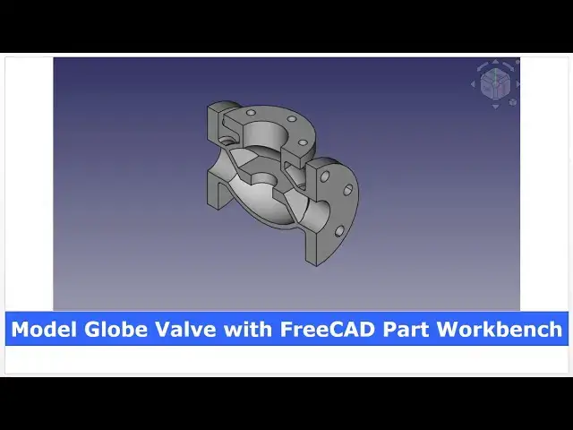
Model Globe Valve with FreeCAD Part Workbench | FreeCAD Tutorial | 3D Modeling | Mechnexus |
May 14, 2025
#freecad #freecadtutorial #learnFreeAD
In this video I have explained How to Model Part in FreeCAD with the help of part design Workbench.
▶️ Get my Complete FreeCAD Course : From Zero to Expert !
https://ko-fi.com/s/1ab4385434
▶️ Join my channel membership and keep supporting my work:
https://www.youtube.com/channel/UCcn6z2whMaFu-_LDsEXCfVA/join
▶️ Visit my website for more info on FreeCAD-:
https://mechnexus.com/
▶️ Download Source File of Tutorial-:
https://mechnexus.com/mechnexus-youtube-tutorial-source-file/
▶️ Buy Me a Coffee
I am very grateful that you watch my videos and I am constantly trying to improve the quality of the videos on this channel. If you'd like to help me do this, please consider supporting me so that I can to continue to produce content for your enjoyment.
👉 Help support this channel by buying me a coffee: https://ko-fi.com/mechnexus
Show More Show Less View Video Transcript
0:00
hello friends welcome to free tutorial
0:03
and in this tutorial we will model this
0:05
uh globe wall in a free with the help of
0:08
a part workbench and i will show you the
0:12
section so this is the internal sections
0:16
of this uh globe
0:18
wallp and i will show you from the
0:21
scratch how you can do the same in
0:24
freead with the help of a part
0:27
workbench if you want to learn free cad
0:30
from the scratch then you can buy my
0:33
complete free cad course from zero to
0:35
expert this course also available on
0:38
udemy but uh problem is that uh udmi
0:42
only give me the
0:44
37% of a course selling you can see here
0:47
user had paid $15 but i have only got $5
0:55
if you wanted to see the review of my
0:57
course you can go to the udemy and s
1:01
search for the free cad and you will see
1:04
my course complete free cad course from
1:06
zero to expert and this course is took
1:09
by the more than 2,000 students and i
1:13
have got the rating of
1:16
4.1 for the demo lectures you can expand
1:19
it and uh see the demo lectures and the
1:24
course structure but i will request you
1:27
if you found my course interesting and
1:31
uh reviews of the other student on udemy
1:35
then i would request you to buy my
1:39
course from the my coffee shops because
1:44
if you buy from here it will help me a
1:47
lot so once you buy my course you will
1:51
be redirected to the google drive and
1:53
here is the my course complete free
1:57
course from zero to expert go inside and
2:01
uh the sections i have shown you on my
2:05
kofi shop page so exactly same lectures
2:11
under the section is created for example
2:15
section one is a introductions to
2:17
freecad 1.0 and what is new in a freecad
2:21
1.0 so if you go to the section one so
2:25
there are the 18 lectures and if you go
2:28
inside of the sections one you will find
2:31
the 18 lecture total and once you go to
2:35
the lecture one you will find a video
2:37
file which you can download to your
2:41
system and you can watch it and this
2:45
course is updated on a equal interval of
2:48
a time once the new feature receives
2:51
came and uh once you purchase the course
2:54
you have the lifetime access to the
2:57
course and in the case of any doubt any
3:00
query you can mail me at
3:05
adminxus.com you can find my course link
3:08
on my youtube channel you can see the
3:11
course link and uh you can also find my
3:14
kofi course page link on uh pin comments
3:19
and uh video descriptions so let's start
3:23
our
3:24
tutorial so i will uh close this file
3:27
and uh create a new file
3:33
now i will create a new file and here i
3:37
will switch to the sketcher workbench
3:41
and i will select the sketcher and i
3:43
will select this uh xy plane and click
3:46
on
3:48
okay now we will uh create our
3:53
sketch so we will uh select the
3:56
threepoint arc first and uh draw the two
4:03
arc and uh i will add the vertical
4:13
relation and i will merge these two
4:17
centers now i will give the radius so
4:21
internal one is
4:24
r90 and uh external one is uh
4:32
97 and now i will move this
4:36
radius to the
4:39
inside and now i will uh select the line
4:46
tool and create my
4:58
profile make it
5:01
horizontal now the same profile we will
5:04
create on the other side
5:18
and we will make it
5:21
horizontal and now we will give the
5:27
dimension so we will select the
5:29
horizontal dimension select the origin
5:32
point and this point give the 100
5:37
mm and we will select the vertical
5:40
dimension select this point and this
5:43
point and give it 77.5
5:52
this we will give the
6:04
20 this will be the 37.5
6:17
37.5 and vertical dimension from this
6:21
point to this point is a
6:33
seven and this point to the origin
6:37
point is a
6:42
25 so now we will constrain on the other
6:46
side the same thing so we will select
6:49
the horizontal
6:50
dimension select this point this point
6:53
and give the 100
6:57
mm select this point this point and add
7:01
the horizontal relation
7:04
select this and this add the
7:08
equal select this and this and add the
7:13
equal also select this and this add the
7:18
equal so our uh sketch is fully
7:21
constrained
7:23
now we will come out of the sketch and
7:28
now we will switch to the part
7:31
workbench and here on a part workbench
7:35
we will click on the revolve tool and
7:39
here zed is one we will make it zero and
7:43
if you see our ucs so we wanted to
7:46
revolve with respect to the x so we will
7:50
give the value one and we will tick mark
7:54
here to create a solid and we will say
7:58
okay so here select the shape of the
8:01
revolution
8:03
so select the sketch and click on okay
8:06
so you can see that uh we have created
8:08
our base feature now we will create our
8:12
next
8:13
feature so for this we will hide it
8:18
ouruh created feature and we will again
8:21
move to the
8:22
sketcher click on the
8:26
sketch and here we will select the xy
8:30
plane
8:32
click on
8:34
okay we will off the our
8:39
body and we will select the polyline
8:49
tool and
8:53
create a rough profile
9:08
and we will make it
9:10
vertical and now we will uh give the
9:13
dimension so we will select horizontal
9:16
define this point to this point 70 mm
9:24
and this one is a
9:31
35.5 this one will be
9:42
18 and from the origin to the top is 80
9:46
mm so select the vertical dimensions
9:50
this point and this point give the
9:54
80 now we will move
9:57
it this one is a
10:04
seven this one will be the
10:08
45 so we have a fully constrained sketch
10:11
and uh we will come out of it and we
10:15
will select our sketch switch to the
10:18
part and here we will revolve it with
10:22
respect to the
10:23
y-axis so we will again select the
10:26
revolve tool and z we will make zero y
10:30
we will give one and we will tick mark
10:33
here create solid and we will say
10:37
okay now we will on our base
10:41
body so here we have a outer shape of
10:47
our globe
10:48
wall if you switch to the isometric
10:51
switch to the top so this is how it will
10:54
look like and
10:57
now these are the two separate
11:01
entities two separate solids so we will
11:04
combine it with the help of a joined
11:07
options so we will select the both these
11:11
two bodies and click on here connect
11:15
object so now you can see that it has
11:19
been merged into the single body
11:25
now we will again switch to the
11:28
sketcher workbench and click on the
11:31
sketcher and here we will again select
11:34
the xy plane and click on the okay and
11:39
we will hide our body and now we
11:44
will create our profile so here i will
11:49
draw the two lines like this
11:52
make it close
12:00
and i will create line like this and i
12:05
will join it and same shape we will
12:08
create on the other side
12:19
now the first thing which we will do is
12:22
add the symmetricity
12:25
constraint so we will use the this
12:28
symmetricity select this
12:31
point this point and origin
12:35
point select this point this point and
12:39
origin
12:41
point select this point this point and
12:46
origin
12:54
point select this
12:56
point this point and origin
13:02
point okay
13:06
now this is the relation which we have
13:09
added and now we will give the
13:11
dimensions so we will click on the
13:14
vertical so first i will give this
13:16
dimension
13:20
16 and here i will add the
13:25
perpendicularity this and this will be
13:27
the
13:30
parallel and
13:35
here i will delete these two line and
13:40
again create a
13:49
line and we will add the
13:52
perpendicularity relation
13:56
we will move this and now we
14:00
will add a parallel relation between
14:03
these
14:06
two and now we will give the
14:09
angle so select the angle select this
14:12
line and this line and give the
14:16
130 select this line click on the
14:20
dimension give it 40
14:28
and select this
14:31
line and give it 7
14:41
mm and select horizontal dimension give
14:45
this
14:47
to this point give the 39
14:52
now i will move my
15:02
dimension so you can see that we have
15:04
given the dimension on one side and with
15:07
the help of relations we have fully
15:09
constrained on the other side now we
15:13
will come out of the sketch
15:16
now we will select our sketch click on
15:19
the extrude and uh we will extrude it to
15:23
the distance of
15:25
120 and we will extrude it to the
15:28
symmetric and check mark on create solid
15:31
and click on
15:33
okay
15:35
now we will expand our connect object
15:40
and here is a revolve our base cage we
15:44
will click on the
15:46
copy go to the edit and click on the
15:50
paste and now we will of this extrude
15:55
and we will edit our this copied sketch
15:59
now we will select everything from right
16:03
to left and make it a construction and
16:07
now here we will create one more profile
16:17
so first i will select the threepoint
16:25
arc and
16:27
now i will select the poly line
16:35
select
16:39
line and
16:43
uh create the similar profile on the
16:46
other
16:48
side join these two
16:54
and select the line and close this
16:57
profile
17:02
now we will make it vertical select this
17:06
and make it
17:07
vertical now we will move this
17:12
dimension and
17:14
now we will constrain it so this
17:18
radius will be 93.5 so we will select
17:22
the radius option and give it uh 93.5
17:35
and we will merge this center so click
17:38
on the
17:45
merge now
17:48
this dimension will be the 28.5
17:56
and we will select these two and make it
18:00
equal and our sketch is fully
18:03
constrained now we will close it and we
18:07
will press the space bar now we will
18:10
revolve it with respect to the
18:13
x-axis so click on the
18:16
revolve give z0
18:19
x1 and click on create solid click on
18:23
okay
18:25
and
18:26
now press the space bar and uh on our
18:31
previous extrude which we have
18:33
created now here we will perform the
18:37
boolean operations so we will select
18:39
these two and uh click on the
18:46
intersection click on the isometric and
18:49
this is how our intersection solid look
18:56
like now we will again switch to the
19:00
sketcher workbench click on the sketch
19:04
and this time we will select this uh
19:06
exit plane and click on
19:09
okay now we will go to the model tab and
19:12
off
19:14
it and now we will select the circle
19:17
tool create a circle and give it a
19:21
radius of
19:25
20 and we will come out of the sketch on
19:28
our body we will select the sketch
19:31
switch to the
19:33
part and uh click on the
19:38
extrude and extrusion length we will
19:41
give the 20 and we will keep it
19:44
symmetric to the
19:46
plane click on
19:48
okay so it is uh coming outside of the
19:52
body now we will again perform the
19:55
boolean operations so we will select
19:57
this body and this body and perform the
20:01
cut so you can see that hole has been
20:04
created
20:08
now we will uh switch to the isometric
20:11
and we will on our previous
20:14
body now we will combine these two this
20:18
connect and this
20:21
cut so click the both and click on the
20:26
union so you can see that it has been
20:29
combined now we will see the internal
20:33
sections how it will be look like
20:36
so we will switch to the
20:38
isometric switch to the top and we will
20:42
see our model in this orientations now
20:46
go to the view tab click on the
20:48
persistent sections and here click on
20:53
the z and click on the
20:56
flip now make it normal so this is how
21:00
our
21:03
sections body
21:05
is we have made with the help of a
21:08
boolean operations and we have used
21:12
the part workbench tool now we will
21:17
close
21:18
it we will off it this section one and
21:22
we can easily see the section whenever
21:24
we
21:26
want
21:31
now for the timing i'm deleting this
21:40
section so this is the not a body so we
21:44
will switch to
21:46
the part design
21:49
workbench and here we will create a body
21:52
and we will select our fusion and drop
21:57
over the body so you can see that base
22:00
feature has been created here and
22:03
now we will create the hole for the
22:08
mountings so we will select this face
22:11
and click on the sketch and now i will
22:15
create a
22:21
circle and uh we will give the vertical
22:23
dimensions select this and this and give
22:27
it a
22:28
55 and
22:30
the radius we will give the
22:34
six click on
22:37
close and now select the sketch click on
22:40
the pocket tool and from drop-down
22:44
select up to face and select this bottom
22:47
face and click on
22:53
okay so you can see that hole has been
22:55
created now we will polar pattern it
22:58
select the pocket and click on the polar
23:01
pattern and here you can see that axis
23:04
automatically selected we will give the
23:07
six
23:08
quantity and click on
23:10
okay now we will create the hole on this
23:14
flange so we will select the face and
23:17
click on the
23:19
sketch and here we will create a
23:23
line and we will give it an
23:27
angle of
23:32
45 and now we will select this line and
23:36
click on the dimension and give it a
23:43
60 and we will make it a construction
23:47
now select the
23:48
circle create a circle and this is of
23:52
radius
23:55
8 so give the eight now close the
24:00
sketch now click on the pocket tool
24:04
click on up to
24:05
face and select this internal
24:09
face and click on okay so you can see
24:12
that uh hole has been
24:15
created now we will again polar pattern
24:18
it the same way we have did it so click
24:21
on here polar pattern and now you can
24:25
see that axis has been selected now we
24:28
will give the quantity six
24:31
click on the
24:32
okay now same hole we will adapt on the
24:36
other sides so we will select the face
24:39
and click on the
24:41
sketch click on the
24:43
isometric now we will click on the
24:46
project geometry and select one of the
24:48
whole
24:50
age so you can see that it has been
24:53
projected here now we will make a normal
24:56
view and create a exact circle what we
25:00
have
25:04
projected now close
25:07
it click on the pocket
25:09
tool from here click on up to
25:13
face and select this inner
25:17
face and click on
25:22
okay so you can see that hole has been
25:24
created now we will again polar pattern
25:26
it select the polar pattern and give the
25:30
quantity
25:32
six click on
25:34
okay so we have adapted the hole now we
25:39
will add some fillet to here so we will
25:43
click on the
25:44
fillet and we will select this
25:51
edge this one this one same way on the
25:56
other
26:00
side this
26:01
one this one
26:05
and this edge and fillet we will give
26:09
the 4 mm click on
26:15
okay switch to the isometric
26:20
so you can see that we have made this
26:22
globe wall with the help of part
26:26
workbench and part workbench is as
26:29
powerful as part design workbench in
26:33
fact we have used the both the
26:34
workbenches to model this part part as
26:38
well as part design workbench so that is
26:40
the beauty of a frecad we can use the
26:43
multiple workbenches to model our part
26:46
now we will see the internal section so
26:49
we will go to the view click on the
26:52
persistent cut and select this z and
26:56
click on the
26:58
flip so you can see that how beautiful
27:02
is our model is in a section view so
27:07
this is all about this tutorial how to
27:11
model the globe wall with the help of a
27:15
part design workbench
27:19
thank you for watching and thank you for
27:21
your valuable
27:24
[Music]
27:40
time heat
27:53
[Music]
28:02
heat heat heat
28:04
[Applause]
28:08
[Music]