live_tv
Livestream Starting Soon
00
Hours
:
00
Minutes
:
00
Seconds
Up next in 10

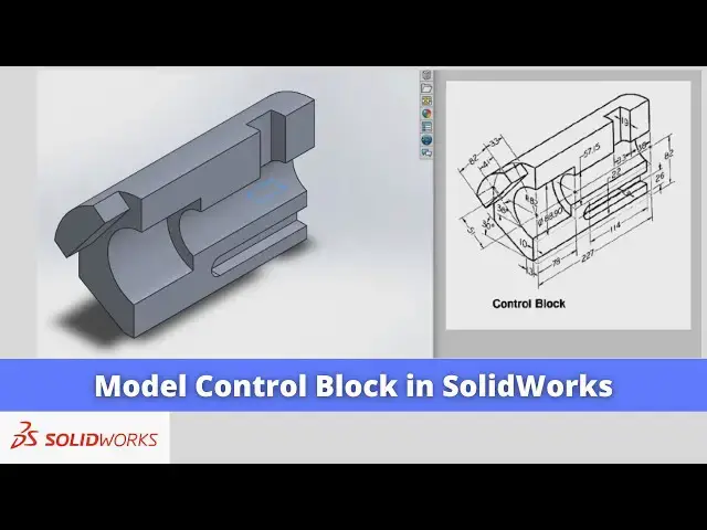
Model Control Block in SolidWorks | SolidWorks Tutorial | SolidWorks Modeling |
Apr 24, 2025
#SolidWorks #solidworksmodeling #solidworkstutorial
In this video I have explained How to Model Control Block in SolidWorks.
▶️ Download This Tutorial Source File From my Ko-Fi Store-:
https://ko-fi.com/s/d8a110f255
▶️ Visit my website for more info-:
https://mechnexus.com/
▶️ The Complete SolidWorks Course : From Zero to Expert!-:
https://www.udemy.com/course/solidworks-complete-course-zero-to-expert/?referralCode=B30458218EA1375DDB6E
▶️ Buy Me a Coffee
I am very grateful that you watch my videos and I am constantly trying to improve the quality of the videos on this channel. If you'd like to help me do this, please consider supporting me so that I can to continue to produce content for your enjoyment.
👉 Help support this channel by buying me a coffee: https://ko-fi.com/mechnexus
👉 Indian User can Support My Work Using my UPI ID: amar.patel456@ybl & amar.patel456@axl
All donations will be used to purchase equipment to improve my productivity and increase the quality of the content that I produce. Your kind support will help to grow this channel. Even if it's just enough to buy me a coffee every little helps and this will be repaid in full through my sharing of knowledge.
Show More Show Less View Video Transcript
0:00
Hello friends welcome to Solid Works
0:02
tutorial and in this tutorial we will
0:05
learn how to model this control Block in
0:09
solid works as we have the isometric
0:11
drawing and we will read the drawing and
0:13
we will create its 3D model in solid
0:16
works you can also visit my website macn
0:20
nexus.com and you can visit this solid
0:24
works tutorials tab where I have written
0:27
so many tutorials on uh solid works
0:30
where you can follow the step by step
0:33
guide to model the
0:36
parts if you like my method of teaching
0:38
then you can also support me on kofi.com
0:41
you can buy me a cup of coffee your
0:45
small support will help these channels
0:48
to grow and it will motivate me to
0:50
create more awesome content on solid
0:53
works so let's come back to our
0:57
tutorial so before creating the drawings
0:59
we will
1:01
read our uh drawing so as we can see
1:04
that uh this is the half section
1:09
part and we can see here the total
1:12
length is a 270 so first we will create
1:17
this outer
1:19
body and we will extrude it to the
1:21
distance of a
1:23
227 and then we will make the rest of
1:27
the internal
1:28
features so let's start our tutorial so
1:32
for this we will uh select this front
1:34
plane and we will uh click on the
1:39
sketch and
1:41
here we can see that uh outer radius is
1:44
r82 and the bore size is a Dia
1:51
88.9 so what we will do we will uh
1:54
create a three-point
1:57
Arc or we will simply create a
2:01
diameter click on the
2:05
circle create a circle and this is the
2:08
r82 so we will select on the smart
2:13
Dimension and we will give it uh 82 * 2
2:20
which is of
2:21
164 and
2:25
now we will select this diameter and
2:28
make it Construction
2:30
which means that this is the maximum
2:33
boundary of this part and
2:37
now internal one is a 88.9 so we will
2:42
also select a circle tool and create a
2:47
circle and uh we will select smart
2:50
Dimension and we will give its diameter
2:54
88.9
3:00
and we will
3:02
also make it a construction so this is
3:06
the maximum internal and outer boundary
3:09
and
3:10
now we will select the line tool and we
3:13
will draw this vertical
3:17
line so if you click on the just snap on
3:21
the center and we will move your cursor
3:24
so you will get the projection line and
3:27
we will draw a line
3:31
and now in the bottom we can see that
3:35
here is a 10 mm Dimension is given which
3:38
is a 10 mm offset from the
3:40
origin so we will draw a vertical
3:47
line and
3:49
uh select smart Dimension select this
3:52
point and origin
3:56
point and we will give here the 10 mm
3:58
dimensions
4:02
and we will move with Dimension to the
4:05
upper
4:07
side
4:10
now from here there is a 13
4:15
mm straight line so we will select the
4:19
line tool draw a
4:25
line select smart dimension
4:30
and uh give the dimension
4:34
13 and now from here there is a line of
4:38
a at a 30°
4:42
angle so we will select the line
4:46
tool create a
4:48
line and give the angle 30° select smart
4:53
Dimension select this line and this one
4:56
and add the angle of a 30°
5:10
now now from the top we can see that it
5:14
is r82 so we will select the three-point
5:17
Arc from
5:20
here and create a three-point
5:27
Arc so it is already
5:30
r82 and
5:36
now we have this 30° line and there is a
5:40
straight
5:41
line so we will move this line to the
5:46
downside and we will select the line
5:49
tool and we will join
5:52
this with this
5:54
one and
5:56
now we will select this line
6:01
and this
6:03
Arc and add the tangent
6:11
relation and we will make this line
6:16
vertical so this is how this profile is
6:20
and
6:22
now we will select the three-point
6:26
Arc select this point and this point
6:30
and select this
6:32
Arc now say okay so we have a fully
6:37
constrain
6:39
profile which we can see it now we will
6:44
come out of the
6:47
sketch press Ctrl 7 for isometric view
6:51
now we will extrude it to the distance
6:55
of
6:56
227 select the sketch go to the feature
7:00
click on extrude
7:03
boss and we will select click on this
7:07
Arrow to reverse the
7:09
direction and give the distance of a
7:19
227 now say
7:25
okay now
7:27
here we have considered this this
7:29
maximum board to the end now if you see
7:36
here here is a bore of
7:41
5715 so that is the minimum bore which
7:45
we require so we will go to the our
7:49
sketch click on the edit
7:54
sketch and we can make this minimum more
7:59
but uh
8:00
as we have considered the maximum bore
8:02
so we have to add the material at this
8:05
portion so we will add the material we
8:08
will not disturb our existing
8:11
sketch
8:15
now now if we see here we have a 78 uh
8:20
Dimension so we will create a plane at a
8:24
distance of a 78 mm from this phas we
8:27
will select this phas and go to the
8:30
reference geometry click on the
8:33
plane and here we will give the distance
8:36
of a
8:37
78 so here it is going outside of the
8:40
body we will uh click on the flip offset
8:44
and click on
8:46
okay
8:48
now we will select this pH and uh create
8:51
a
8:53
sketch and we will select this age and
8:57
click on the convert geometry
9:03
now we will make this phase normal now
9:07
internal boore is a 57.1 5 so we will
9:11
click on the circle tools draw a
9:16
circle and uh select smart
9:20
Dimension and uh give it a diameter of
9:23
57.1 15
9:31
and
9:32
now we will draw the two lines at a
9:35
bottom and a top and we will trim the
9:38
rest of the
9:43
geometry now select the line tool and
9:47
uh draw the
9:50
line and now we will click on the trim
9:54
entities and select here trim to
9:57
closest and trim
10:01
say okay come out of the
10:05
sketch press control 7 and now we
10:11
will add the material we will select our
10:14
sketch click on the extrude boss and
10:18
base now we will reverse the directions
10:21
from here we will select up to surface
10:25
and we will select the back side of the
10:27
surface
10:29
and click on
10:32
okay so you can see that now we have a
10:35
similar feature here now we will select
10:38
the plane and click on hide
10:42
icon now press the control
10:45
7
10:47
now we will create this boss for this we
10:52
will select this face and click on the
10:56
sketch and we will make this face normal
11:00
and
11:01
now if we can see here we can see the
11:05
dimension it is a 33 and this is the
11:08
82 so we will first select a three-point
11:12
Arc and draw a three-point
11:21
Arc or we will delete this Arc first we
11:25
will project our Outer
11:27
Edge and uh we will make it
11:32
construction and now we will select the
11:35
three-point
11:39
Arc and create an arc equal to our
11:43
projected
11:44
Arc and
11:50
now here is a distance 82 is given and
11:56
uh from Center it is 41 this which means
11:59
that this 82 is a
12:01
symmetric and
12:03
now here we can see that he angle is
12:06
given is uh
12:09
38° so we will select the line
12:13
tool we will uh create a construction
12:21
line select it and make it
12:26
construction and uh draw the to
12:29
approximate
12:34
line similarly on the other side as well
12:38
select a line
12:40
tool and close this
12:46
profile okay and now this angle is a 38
12:50
so first we
12:52
will give the angle
13:02
38° and now this line and this line have
13:06
the parall relation so we will select
13:09
these two
13:11
lines and give the parallel
13:14
relation and this line and this line
13:19
will have the perpendicular
13:24
relation now
13:30
we will move
13:32
it now total distance is 82 so we will
13:36
select smart
13:42
Dimension and we will give the dimension
13:53
82 now we will move this line to the
13:56
downside
14:02
and move
14:04
it now we will move this line to the
14:08
upper side
14:15
here and if you see our drawing here is
14:18
a dimension 51 is
14:23
given
14:25
so we will select a line tool
14:31
and we will uh draw a
14:34
line and make it
14:38
construction and we will select this
14:42
line or we will add
14:45
the dimension of a 51
14:59
we will move the
15:01
angle
15:03
here and
15:06
now this line and this line will have
15:09
the parallel
15:11
relation select this line and our
15:14
construction line and add the parallel
15:17
relation so we have a fully constrained
15:24
profile now we will select the smart
15:27
dimension select this one and this one
15:30
which is a
15:33
41 and
15:36
now we will come out of the
15:41
sketch press contrl 7 for
15:45
isometric and click on extrude
15:48
boss and this is of a 33 distance so
15:52
give the dimension
15:54
33 click on
15:56
okay so we have created this profile as
15:59
well and
16:01
now we will create this
16:04
cut we will select this pH and click on
16:08
the
16:10
sketch we will make this face
16:14
normal and now we will uh select a
16:17
simple
16:19
rectangle and create a
16:23
rectangle we will delete this line we
16:27
will select the three-point Arc
16:30
create a three-point
16:34
Arc now from the AG to the center is a
16:38
114 we will select this point and this
16:45
line and add the dimension of
16:49
uh
16:55
114 and the center to the edge is
17:00
26 so we will select this point and this
17:04
age and give the dimension of
17:16
26
17:18
now if we see here it is a cut depth of
17:22
13 and its uh diameter is a 22 so we
17:27
will select these two lines
17:29
and add the dimension of
17:36
22 so we have a fully constrained
17:39
profile now we will come out of the
17:43
sketch press control
17:45
7 select the sketch and make a cut of 13
17:50
mm click on extrude
17:53
Cut and give the distance of 13 mm
18:00
click on
18:01
okay now we have a one cut here for this
18:08
we will select this uh
18:10
our top plane and uh click on the
18:16
sketch press Ctrl 7 and
18:20
now it is a cut of 33 by1
18:26
19 so we will uh make this pH
18:31
normal we will switch to the wireframe
18:38
view we will select a rectangle
18:42
tool and create a
18:46
rectangle and from this age it is a 19
18:50
so we will select smart
18:54
Dimension and give it a distance of 19
18:57
mm
19:01
and this horizontal is a
19:12
33 and the from age it is a 38 so we
19:16
will select this line and this age and
19:19
we will give the
19:24
38 now we will switch to the Shaded View
19:29
press contrl
19:31
7 come out of the
19:36
sketch select the sketch click on
19:39
extrude
19:41
Cut and here we want cut in a upper side
19:46
so we will click on this Arrow flip his
19:49
Direction and we will say simply through
19:51
all say
19:54
okay so you can see that uh we have a
19:58
completed the model of this uh control
20:01
Block in solid
20:04
works and this is all about this
20:07
tutorial how to model control Block in
20:09
solid works thank you for watching and
20:11
thank you for your valuable time