live_tv
Livestream Starting Soon
00
Hours
:
00
Minutes
:
00
Seconds
Up next in 10

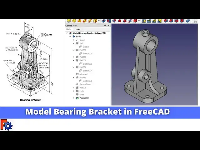
Model Bearing Bracket in FreeCAD | FreeCAD Tutorial | FreeCAD Part Design | Mechnexus |
May 16, 2025
#freecad #freecadtutorial #freecadpartdesign
In this video I have explained How to Model Part in FreeCAD with the help of part design Workbench.
▶️ Get my Complete FreeCAD Course : From Zero to Expert ! on Ko-fi
https://ko-fi.com/s/1ab4385434
▶️ Get my Complete FreeCAD Course : From Zero to Expert ! on Udemy
https://www.udemy.com/course/freecad-course-for-beginner/?referralCode=3BA9B526A12F96295D44
▶️ Join my channel membership and keep supporting my work-:
https://www.youtube.com/channel/UCcn6z2whMaFu-_LDsEXCfVA/join
▶️ Visit my website for more info on FreeCAD-:
https://mechnexus.com/
▶️ Download Source File of Tutorial-:
https://mechnexus.com/mechnexus-youtube-tutorial-source-file/
▶️ Buy Me a Coffee
I am very grateful that you watch my videos and I am constantly trying to improve the quality of the videos on this channel. If you'd like to help me do this, please consider supporting me so that I can to continue to produce content for your enjoyment.
Show More Show Less View Video Transcript
0:00
Hello friends Welcome To fread tutorial
0:03
and uh in this tutorial we will model
0:05
this bearing bracket in fread as you can
0:08
see that uh I have already modeled it
0:12
with respect to the isometric drawing of
0:14
a bearing bracket and I will show you
0:17
from the scratch how you can do the same
0:21
in freead with the help of a part design
0:23
workbench so let's start our
0:28
tutorial
0:32
now I will uh close this file and I will
0:35
create a new
0:36
file and uh before starting we will read
0:40
our drawing how we are going to
0:43
proceed so first uh we will make this
0:46
base
0:48
feature and after that uh we will make
0:53
this uh
0:55
rib and we will make this round features
0:58
and at the last we will adapt all these
1:03
holes so here I have uh activated the
1:06
part design workbench and
1:10
now I will uh insert a
1:13
body and I will on my plane and from
1:17
here I will select the XY plane and
1:19
create a
1:23
sketch and now I will uh create a
1:28
rectangle
1:31
and uh I will make it uh symmetric so
1:35
for symmetricity I will uh select this
1:39
point this point and origin point and
1:43
now I will uh give my
1:46
Dimension so this is the 84 so I will
1:49
select it and give it
1:52
84 and this one is a
1:58
70 so this is this is our base features
2:01
and uh if you see our drawing we can see
2:03
that uh it is a 11 mm
2:06
thick oh I will close my sketch and
2:10
click on the
2:11
pad and I will give my thickness 11 mm
2:14
and say
2:17
okay now I will on my
2:21
plane and I will switch to the isometric
2:24
and
2:26
now we will create this middle features
2:29
on our mid plane y z so I will select
2:33
the plane and create a
2:38
sketch and I will switch to the
2:41
isometric
2:42
View and first thing which I will do is
2:45
uh I will project my
2:48
age and now I will select the line
2:53
tool and
2:55
uh create a
2:58
line
3:02
so this is not merge so I will select it
3:05
and say
3:06
merge and now I will
3:10
uh create a circle at a height of 162
3:16
which we can see
3:23
here and this circle OD would be 46 so I
3:29
will select this circle and uh give the
3:32
diameter dimension of
3:37
46 and from the bottom it is a 162 at
3:41
the top but if you see the center is a
3:45
133 so we have origin point and circle
3:49
origin point and we will give the
3:51
dimension
3:54
133
3:57
now we will make it constru
4:00
instruction and now I will uh create a
4:03
two
4:07
line
4:09
randomly and I will move this line
4:11
outside of the
4:14
circle and I will select these two and
4:19
uh make it tangent and we will do the
4:23
similar thing here we will make it a
4:27
tangent and uh we have the two option
4:31
either we can trim or we can make a Arc
4:34
and point constraint so we will go with
4:36
the trim and we will trim
4:40
it so
4:44
here if it trim then it is getting whole
4:48
line get disappeared so what we will do
4:50
we will select this Arc and point and
4:53
make it
4:55
coincidence and we will create a
4:58
three-point Arc
5:10
and we will create one
5:18
Arc so we have a fully constrained
5:21
sketch now we will come out of the
5:25
sketch and uh we will extrude it to the
5:29
8 mm we can see here the thickness is 8
5:32
mm so we will select the sketch click on
5:35
pad and view our Dimension 8 mm and we
5:39
will keep it symmetric to the plane and
5:41
we will say
5:43
okay so these are the two features which
5:45
we have draw now we will move to the
5:48
next feature so the next feature is this
5:51
uh round so we will again on our plane
5:56
and if you see here we have the mid
6:00
plane passing through our
6:03
body so we will select this plane and uh
6:06
create our sketch so we will select this
6:08
y z plane and click on sketch and
6:13
now I will off the
6:16
plane now we will project the
6:19
geometry and now I will uh create a
6:25
circle and one more
6:28
Circle
6:30
so Outer Circle is automatically got
6:33
constrained with our projector geometry
6:35
now the inner one is a
6:39
28.57 so we will select it and
6:43
uh give the diameter of uh
6:50
28.57 now we will close the
6:54
sketch and now we will read the
6:57
dimension so we can see that it is a 34
7:00
it is a symmetric from the center to the
7:02
age is 17 so we will select the sketch
7:06
click on the
7:07
pad and we will give the dimension 34
7:10
and we will keep it symmetric to the
7:12
plane and we will say
7:15
okay now we will move to the next
7:19
feature now our next feature is this rib
7:23
which we can see here so for this we
7:26
will again on our origin plane and we
7:29
can see that if you see from the right
7:32
side we have the mid plane so we
7:36
will select this exit plane and uh
7:40
create a sketch now go to the model tab
7:43
of the plane and now here first thing
7:47
which we will do is uh we will project
7:50
the
7:50
geometry so I will project this
7:53
age and
7:56
uh I will also project this age for
8:00
better visibility I will go to the
8:03
wireframe and now here we will read the
8:07
dimensions so we can see here if you
8:10
zoom our uh model so we can see here
8:14
here is a radius
8:19
R32 and
8:23
uh it is
8:27
a 10 mm which we can see
8:31
here so we
8:35
will create a
8:39
line and then we will create a
8:41
three-point
8:45
Arc and first thing which we will do we
8:47
will merge
8:49
this Arc
8:51
point and we will add the tangency
8:57
relation and we will also make this
9:05
tangent so here we can see the dimension
9:09
10
9:10
mm so I will select this point and our
9:14
origin
9:15
point and give the dimension of 10
9:18
mm and
9:23
now I will uh select a line
9:27
tool and I will draw a horizontal line
9:31
and I
9:33
will draw a vertical line now we have
9:37
the projected geometry here so we will
9:40
again draw one
9:44
line and we will merge these two
9:50
points and we will select this point and
9:53
line and make it
9:54
coincidence now
9:56
here we will make this geometry
9:59
construction and we will draw one more
10:04
line so we have the
10:09
fully constraint
10:13
sketch now we will uh switch to
10:17
the flat
10:19
lines and we will come out of the
10:24
sketch and we will click on the
10:26
pad and from here we will will select
10:30
symmetric to the
10:31
plane now we will see the thickness of
10:35
our this created sketch so if we Zoom it
10:39
then we can find it it is a 8 mm thick
10:42
so we will give the dimension 8
10:46
mm and we will keep it symmetric to the
10:49
plane and click on
10:52
okay now the next
10:57
feature now our next next feature is we
11:00
will create this boss so for
11:04
this we will uh select the mid
11:12
plane and we will again select this YZ
11:15
plane and create a
11:18
sketch now we will switch to the
11:21
wireframe
11:23
view now we will select the
11:27
circle and create a approximate circle
11:31
now we will uh read the
11:40
dimension now if we see our model then
11:45
here is a radius given r81 which is a
11:50
passing through this Center so for this
11:53
we will uh
11:55
project this circle and we will uh
11:58
create a
12:00
circle and we will give it the
12:06
diameter 81 * by 2 and
12:10
now we will add the
12:15
relation so we can see that we have
12:17
found one dimension but it can move on
12:20
Arc anywhere so we will fix the
12:24
position so if you see it is a 14 mm
12:29
from the center here it is given so we
12:31
will select this and uh select this
12:35
these two points and add the horizontal
12:38
dimension of 14
12:40
mm and now we will uh add the diameter
12:44
which is of uh
12:49
29 we will select
12:57
it so if we Zoom it then we can find
13:01
that it is a 29 diameter now the circle
13:06
which we have created we will make it
13:10
construction and now I will switch to
13:13
the
13:16
isometric of my plane and come out of
13:19
the
13:20
sketch now if you see the Extrusion
13:23
Dimension so it is a 33 total and from
13:26
the center one side it is a 7
13:30
so we will select the
13:32
sketch switch to the flat lines and
13:35
click on the pad and from drop down we
13:38
will select the two
13:40
Dimensions at One Direction it is a
13:46
17 and uh other direction it will be the
13:52
16 so just to check the dimension we
13:55
will add uh 170 so this this is the 17
14:00
which is the right so I will remove this
14:02
zero that is for only checking purpose
14:05
now I will close
14:07
it so you can see that we have added the
14:10
boss now we will move to the next
14:13
feature now if we see our model we can
14:17
see a note here is that identical rips
14:20
on both the sides so we will find out
14:25
our
14:26
rips so this pad 00 03 is our rib and we
14:30
will mirror it so for
14:33
this click on the mirror tool and click
14:37
on pad
14:39
003 and click on okay and from here you
14:44
can see that uh it automatically took
14:47
this YZ plane and mirror it but it is
14:51
recommended to manually select the plane
14:54
select reference and select this y z
14:57
plane and click on
14:59
okay so you can see that we have mirror
15:04
the rib now we will move to the next
15:09
feature now we will uh select this pH
15:13
and uh create this hole so for this I
15:16
will create a sketch and I will project
15:20
the
15:20
geometry so that I get a center now I
15:25
select the circle tool and create one
15:27
Circle
15:29
so this is of the bore of the 13 mm
15:33
drill so you can make with a whole
15:36
feature as well but I am going to use
15:39
the extrude cut feature so now I will
15:43
give it a diameter of 13 mm now I will
15:46
close it and uh I will click on the
15:49
pocket tool and I will set it through
15:52
all let's say
15:55
okay now we will uh move to to the next
16:00
feature so next feature is we will
16:03
create this boss so we can see that from
16:06
the bottom it is a 162 so we will uh on
16:10
our origin plane and we will create a
16:13
datm plane so I will select my Base
16:16
plane and click on the datm plane
16:20
options and from
16:23
here in a z Direction I will enter this
16:26
value 162
16:32
so you can see that a data plane has
16:34
been created click on
16:37
okay
16:39
now here is a rebuild options so rebuild
16:44
it you can also click on Mark to
16:47
recompute so that it will recompute
16:50
whole
16:51
body now select the datm plane and uh
16:55
click on the
16:57
sketch and here it is at the center so
17:02
here I will uh draw the circle of uh 17
17:12
mm select the diameter option and give
17:15
it a diameter of a
17:17
17 close
17:19
it and uh select the DAT temp plane
17:22
press the space bar key and hide the
17:24
data plane now select the created sketch
17:28
and uh click on the
17:30
pad you will not see anything here
17:34
because it is a EXT extruding in
17:37
opposite directions so click on here
17:40
reverse and here you can see that now we
17:44
are seeing our pad go to the drop
17:47
down click on up to pH and select this
17:51
pH so that is the int
17:54
conditions so that our pad will be stop
17:56
on this surface and click click on
18:00
okay now we will uh move to the next
18:05
feature our next feature is to create
18:09
the M8 hole of page
18:13
1.25 so for this I will select this pH
18:16
and create a sketch and here I want a
18:21
emit hole so simply I will select the
18:24
circle and uh create a circle and it a
18:30
dimension of 8 mm now I will close
18:33
it and now I will use the whole
18:39
tool and here I will select the iso
18:44
matric regular
18:48
profile and here I will select my size
18:51
which is of
18:57
M8
19:01
and I will give the
19:04
distance so this is the 28 and this is
19:08
the 46 so this thickness will
19:14
come so uh this thickness will come uh
19:17
2886
19:19
so 18 mm so roughly if I give here 25 mm
19:25
that is fine because we do not have the
19:27
IND condition option else we have
19:30
selected this pH so it should pass
19:34
here that is fine and here you can set
19:37
your drill Point flat or angle so I will
19:39
go with a fat flat
19:42
drill and say okay now if I go to the
19:47
whole feature
19:50
here so you will see the your whole
19:55
profile like uh it is a Mt
20:00
hole custom values cut diameter cut
20:03
depth and here is a threaded
20:07
features so it is false and you can set
20:10
it
20:12
true and go to the
20:20
isometric now let's move to the next
20:27
feature
20:29
our next feature is to add the fillet to
20:33
our uh base
20:35
plate so this is of
20:39
r18 so we will select the fillet
20:42
options and we will give here value
20:48
18 and we will click on select and we
20:51
will select the all four
20:53
edes and we will rotate our
20:57
model
21:02
and click on okay so you can see that
21:05
fillet has been
21:07
added now our next step is we will add
21:10
these four drill
21:12
holes so for this I will uh select the
21:16
face and uh create a
21:20
sketch so these are
21:23
the drill holes of uh 8 mm size so I'm
21:28
not going to use the whole tool I am
21:31
going to use with the
21:35
pocket so here I will uh select a
21:39
rectangle for my convenience and I will
21:43
uh go to the wireframe it is my practice
21:47
so that uh with a rectangle I can
21:48
control the positions and uh this
21:52
rectangle will be the
21:54
construction and now I will make it
21:57
symmetric I I will select this
21:59
point this point and my origin point now
22:04
I will give the
22:05
dimensions so if you see here it is a 58
22:09
and it is a
22:13
46 so I will select this line and I will
22:16
add the dimension
22:18
46 and I will select this line and add
22:21
the horizontal dimension of
22:26
58 now
22:29
I will uh create a four
22:38
Circle and I will select all the circles
22:42
and make it
22:45
equal and I will give the one of the
22:47
circle my drill size which is of 8 mm so
22:52
you can see that uh my all Circle are
22:55
got constrained and Bas part of uh using
22:58
this rectangular sketches you can easily
23:01
modify the dimensions if you change this
23:05
Dimension then your rectangle get
23:07
modified and your whole Position will
23:09
get
23:10
changed so this is the my practice you
23:13
can use uh your method now we will
23:17
switch to the flat lines and we will
23:19
select our sketch and click on the
23:22
pocket tool and we will say it through
23:25
all and say okay
23:29
now you can see that uh we have
23:32
completed our model there is a a common
23:36
note of a fillet so you can see here all
23:41
fillets and rounds are the R3 which
23:44
means that uh you have to add the fillet
23:47
to the all ages of R3 which I'm not
23:50
going to add because uh this will takes
23:53
too much time so this is how we have
23:57
model bearing bracket in freead with the
24:00
help of a part design
24:02
workbench so this is all about this
24:05
tutorial how to model bearing bracket in
24:08
freeat thank you for watching and thank
24:10
you for your valuable
24:14
time you can also visit my website Mech
24:17
nexus.com where I write articles and
24:21
tutorials on freead you can download my
24:25
tutorial source file from the here if
24:28
you like my method of teaching then
24:30
please support me on coffee.com you can
24:34
buy me a cup of coffee your small
24:37
support will help these channels to grow
24:39
and it will motivate me to create more
24:42
awesome content on feat
#CAD & CAM