live_tv
Livestream Starting Soon
00
Hours
:
00
Minutes
:
00
Seconds
Up next in 10

#freecad #freecadtutorial #freecadpartdesign
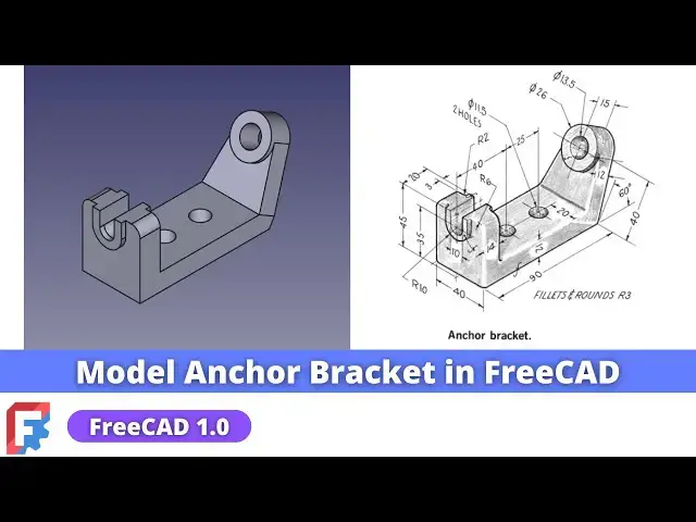
In this video I have explained How to Model Anchor Bracket in FreeCAD.
▶️ Visit my website for more info on FreeCAD-:
https://mechnexus.com/
▶️ Get my FreeCAD Crash Course for beginner-:
https://www.udemy.com/course/freecad-course-for-beginner/?referralCode=3BA9B526A12F96295D44
▶️ Download Source File of Tutorial-:
https://mechnexus.com/mechnexus-youtube-tutorial-source-file/
▶️ Buy Me a Coffee
I am very grateful that you watch my videos and I am constantly trying to improve the quality of the videos on this channel. If you'd like to help me do this, please consider supporting me so that I can to continue to produce content for your enjoyment.
👉 Help support this channel by buying me a coffee: https://ko-fi.com/mechnexus
All donations will be used to purchase equipment to improve my productivity and increase the quality of the content that I produce. Your kind support will help to grow this channel. Even if it's just enough to buy me a coffee every little helps and this will be repaid in full through my sharing of knowledge.
Show More Show Less View Video Transcript
0:00
Hello friends welcome to Freer tutorial
0:02
and in this tutorial we will model this
0:05
uh anchor bracket as you can see that I
0:08
have already modeled it and I will show
0:10
you from the scratch how you can model
0:13
this part to model this part I am using
0:16
the freead
0:18
1.0 if you have not this latest version
0:22
of freead install
0:24
it so let's begin our tutorial I will
0:27
close this file and create a new file
0:30
you can also visit my website Mech
0:33
nexus.com where I write articles and
0:36
tutorials on freead you can download my
0:39
tutorial source file from here tutorial
0:42
source file page and you can also
0:45
support me by buying a cup of coffee on
0:50
kofi.com your uh small support will help
0:54
these channels to grow and it will
0:56
motivate me to create more awesome
0:58
content on freead
1:00
I thanks to all my supporter those who
1:03
have supported me by buying a cup of
1:07
coffee so keep supporting and uh it will
1:11
help me to grow this Channel and it will
1:16
motivate me to create more awesome and
1:18
useful tutorials on freeat so let's come
1:22
back to our
1:23
tutorial so here I have created a new
1:26
file and I will insert the body and I
1:30
will on my
1:31
plane and we will read our drawing so if
1:35
you see our
1:36
drawing so if we start our sketching
1:39
from the right plane and extrude this
1:42
profile to the 40 mm that will be good
1:45
so we will select this right plane and
1:47
click on the
1:49
sketch go and hide uh datm
1:53
plane and
1:56
now I will select a rectangle tool
2:02
I will uh create a
2:04
rectangle select a line
2:10
tool and here I will use the trim option
2:15
to trim this this and I will also delete
2:20
this and now I will select uh again
2:24
polyline
2:25
tool and create a rough profile
2:32
and now we will apply the suitable
2:34
constraint so first thing is uh I will
2:38
select this and this and add a parallel
2:42
constraint select this and provide the
2:45
horizontal dimension of uh 90
2:53
mm this is of the
2:58
45 this is is of the
3:03
14 and from this point to this point is
3:09
of 12
3:14
mm so perpendicularity is
3:18
added now select the dimension and add
3:23
align dimension of 53
3:30
and uh this
3:32
angle is of
3:37
60° and this is of 12
3:43
mm so the beauty of a free cat 1.0 is
3:46
that uh dimensioning is uh too much
3:50
convenient because uh in a previous
3:53
version of a free
3:56
cat
3:57
0.21 we have to select the respective
4:00
Dimension horizontal or vertical then
4:02
give the dimension but here it is a
4:05
smart so once you select the dimension
4:08
tool it automatically detects the type
4:10
of
4:11
Dimension now we will uh move towards
4:14
the next feature which is to extrude the
4:17
profile to the 40
4:19
mm so we will come out of the
4:24
sketch and click on the pad click on
4:28
symmetric to the place Lane and add the
4:32
dimension of 40
4:34
mm and click on
4:36
okay now we will uh move to the next
4:40
feature which is the material removal we
4:44
will uh remove the material at uh this
4:46
portion so for this we will uh select
4:50
the ph and uh click on the
4:55
sketch and we will click on the project
4:58
geometry
5:00
we will project this we will also
5:03
project this and uh we will create a
5:06
circle and uh this circle will be the
5:09
construction
5:11
Circle and uh which is of a diameter
5:16
26 so select the dimension and provide
5:19
the
5:22
26 and now we will select this and this
5:26
and add a tangent
5:29
and now
5:32
here we will uh create the
5:38
profile so first thing we will select a
5:41
line tool and uh create a line first
5:45
thing is stream is not possible so we
5:48
will make it a
5:52
coincidence and now we will select a
5:54
threo Arc
6:03
first thing we will make this and this
6:10
horizontal and now we will close our
6:15
profile join this with this and select a
6:20
Treepoint
6:25
Arc now
6:27
here we will find out the issue so we
6:30
will select this and this and made it
6:33
equal so our profile is fully
6:36
constrained and now we will remove this
6:40
profile material up to this pH so click
6:44
on the cut and select up to face and
6:48
select this face click on okay now we
6:53
will mirror this and we have the mid
6:55
plane so we will select this uh YZ plane
7:00
so select the pocket and click on the
7:03
mirror and uh here select
7:08
transform shape so we will select a
7:11
reference and select this mid plane
7:15
click on
7:16
okay and now we will off our data plane
7:21
now we will move towards the next
7:23
feature and our next feature is to
7:27
provide the fillet which is our of R six
7:31
here so we will select this and this and
7:35
click on the
7:37
fillet and provide the value of R
7:43
six now we will uh create here the
7:47
slotted cut so we will select the phase
7:51
and uh click on the
7:53
sketch and uh we will rotate our model
7:57
click on the project geometry
7:59
and uh we will select a rectangle
8:04
tool and
8:06
uh we will delete this line and create a
8:10
three-point Arc and then we will add a
8:15
tangency select this hand is tangent
8:19
this hand is tangent and uh we will make
8:23
this
8:24
symmetric and give the dimension of 10
8:26
mm so select this
8:29
this and this
8:31
axis
8:33
and provide the dimension of 10 mm so
8:37
keyboard shortcut is a d for the
8:40
dimension and
8:43
now we will
8:45
provide this vertical dimension of 35
8:50
mm so our sketch is fully constrain we
8:54
will uh come out of the sketch click on
8:57
the
8:57
cut select uh up to pH and select this
9:02
inside pH click on
9:07
okay now we will move towards the next
9:12
feature which is to add a
9:16
material for this boss so we will select
9:19
the phase and click on the
9:21
sketch and click on the project geometry
9:25
and here is a keyboard shortcut GX
9:29
but I will use the icon and now I will
9:33
uh select the circle and uh create this
9:36
profile come out of the sketch and we
9:39
will uh extrude it to the distance of 3
9:42
mm which which we can see
9:45
here 15 - 12 is 3 so click on
9:50
extrude and uh provide the 3
9:53
mm beauty of a fread 1.0 is that it
9:58
automatically merg the feature is it's
10:01
automatically set it to the refine is
10:05
true so here in uh freat 0.21 we have to
10:11
do it
10:13
manually now let's uh move towards to
10:17
the next feature with uh respect to our
10:19
drawing which is to create a hole of
10:24
13.5 which is given here so we will
10:27
select the phase and click on the
10:29
sketch and uh we will simply project the
10:34
diameter so that we get the center and
10:36
we will create a
10:38
circle and we will select a diameter and
10:42
uh this is off a diameter
10:46
13.5 click on
10:48
close click on
10:52
Cut say it through all click on
10:56
okay now
10:59
we will move to the next feature which
11:02
is to add a
11:04
material in this slotted area so we will
11:08
select the phase and we will project
11:10
this geometry so we will select the
11:12
phase and click on the sketch we will uh
11:15
rotate it we will uh select the project
11:19
geometry and we will project this Arc
11:22
and a vertical
11:24
line and we will create exact profile
11:30
as we project it so here is a
11:33
three-point Arc so we will create a
11:36
3point
11:38
AR and
11:41
select this and this and made it uh
11:45
equal select a
11:48
line close the profile and we will
11:52
create
11:54
offset and first we will give the radius
11:58
of uh R 10 so give it to 10 mm and
12:04
now we will connect this with this and
12:08
apply the vertical Dimension select
12:11
this select this select this and provide
12:17
it a
12:20
vertical this is the
12:24
horizontal with respect to our Cube this
12:28
will will be also the
12:34
horizontal and
12:37
now let's add the tangency
12:44
here and let's see what is done un
12:52
constraint so select this point and this
12:56
line and add a coincidence so our
12:59
profile is fully constrained now we will
13:02
extrude it to the distance of 3 mm so we
13:05
have already selected the
13:07
skage click on extrude and set 3
13:13
mm click on okay now we will uh mov to
13:18
the next feature which is to the mirror
13:22
this pad which we have it so for this we
13:25
want to mirror on the other side as we
13:29
we can see here but we require a plane
13:32
so if we select this AG so we can see
13:35
the dimension is a 14 mm so we will
13:38
select the phas and uh create a datm
13:41
plane at a distance of uh 7
13:46
mm and uh set it to the
13:50
minus click on okay now here is a Blue
13:53
Tick so we will rebuild it and now we
13:56
will select the pad and click on the the
13:59
mirror option and from here we will
14:02
select the reference and we will select
14:06
this datm plane and click on the
14:10
okay now we will off the datm plane now
14:14
we will move to the next feature which
14:17
is to create a
14:19
hole these two holes which we can see
14:21
here so we will select the face and it
14:24
is a plain drill hole so I will make
14:26
with a cut tool so I I have selected the
14:29
ph and I will create a
14:32
sketch and uh I will create a two
14:37
circles and we will give the
14:39
dimensions so first we will select this
14:43
two by pressing the control key and we
14:45
will make it equal and we will select
14:47
the smart Dimension and provide the
14:50
dimension of
14:53
11.5 click on okay and uh Center to
14:57
Center distance is of
15:00
25 and from age it is 40 so we will
15:05
click on the project geometry and
15:07
project
15:08
this and select the dimensions tool
15:11
select this and this and uh provide the
15:15
dimension of uh 40
15:19
mm let's press zero for
15:26
isometric so our sketch is fully
15:29
constrained as you can see
15:32
that 40 and 25 click on
15:36
close select the sketch click on
15:40
Cut and simply say it through
15:45
all so this is how we have modeled this
15:49
anchor bracket uh from the
15:51
scratch and uh this is all about this
15:55
tutorial thank you for watching and
15:58
thank you than you for your valuable
16:00
time
#CAD & CAM
#Jobs & Education