live_tv
Livestream Starting Soon
00
Hours
:
00
Minutes
:
00
Seconds
Up next in 10

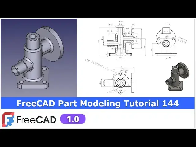
FreeCAD Part Modeling Tutorial | FreeCAD Tutorial 144 | 3D Modeling | Learn FreeCAD | Mechnexus |
Apr 24, 2025
#freecad #freecadtutorial #learnFreeAD
In this video I have explained How to Model Part in FreeCAD with the help of part design Workbench.
▶️ Join my channel membership and keep supporting my work:
https://www.youtube.com/channel/UCcn6z2whMaFu-_LDsEXCfVA/join
▶️ Visit my website for more info on FreeCAD-:
https://mechnexus.com/
▶️ Get my FreeCAD Crash Course for beginner-:
https://www.udemy.com/course/freecad-course-for-beginner/?referralCode=3BA9B526A12F96295D44
▶️ Download Source File of Tutorial-:
https://mechnexus.com/mechnexus-youtube-tutorial-source-file/
▶️ Buy Me a Coffee
I am very grateful that you watch my videos and I am constantly trying to improve the quality of the videos on this channel. If you'd like to help me do this, please consider supporting me so that I can to continue to produce content for your enjoyment.
👉 Help support this channel by buying me a coffee: https://ko-fi.com/mechnexus
Show More Show Less View Video Transcript
0:01
hello friends welcome to fread tutorial
0:03
and in this tutorial we will model this
0:05
part and you can see that uh I have
0:09
already modeled it in a frecad and it is
0:11
a matching with the isometric view now
0:15
we will create this part from the
0:17
scratch and for this tutorial I'm using
0:20
the frecad version 1.0 so you must have
0:24
at least fread version 1.0 zero or
0:27
higher version of a free
0:29
card now I will close this file and
0:32
create a new
0:34
file you can also visit my website
0:38
macexus.com where I write articles and
0:42
tutorials on freead and you can also
0:45
access my 3D part library of a free you
0:51
can download the part from here and you
0:54
can use in your projects with
0:58
modifications you can also access my 2D
1:01
drawing library where you can u download
1:05
this 2D drawings and uh you can create
1:10
3D models with respect to these
1:14
drawings you can also support me on
1:18
coffi.com you can buy me a cup of coffee
1:22
your small support will uh help this
1:25
channels to grow and it will motivate me
1:28
to create more awesome content on uh
1:31
free CAD you can find my Kofi donation
1:34
page link in a video description as well
1:38
as you can also see my Kofi page URL on
1:42
this
1:43
header so let's come back to our
1:46
tutorial
1:50
now I have created a new file and here I
1:54
will insert my body and on the origin
1:59
plane and now if you see our model so we
2:03
will uh create our first sketch on a
2:06
right
2:07
plane so here select the right plane and
2:11
click on the
2:12
sketch and now I will off the origin
2:16
plane and uh I will uh select a polyline
2:20
tool and uh create a rough
2:33
profile and
2:35
now let's constrain this so if you see
2:39
here here is a diameter 40 is given so
2:43
we will add a radius of a
2:48
20 and let's move this dimension and
2:52
total height is of 115 which we can see
2:56
here so select it and uh provide it
3:02
115 and
3:04
uh this diameter is of a 30 so this will
3:08
become
3:10
15 and
3:12
uh let's move this
3:17
line so
3:20
here diameter 13 so instead of a 25 it
3:24
was a typing error give it 15 and now
3:30
let's constrain this height
3:33
select
3:35
uh this line and provide here 25
3:39
mm so we can see that uh our uh sketch
3:42
is fully constrained and
3:46
now we will close it and we will uh
3:50
create a revolution around the Z axis so
3:56
select the sketch click on revolve so
3:59
you can see that uh fread automatically
4:01
took the reference
4:03
of now we will uh create this bottom
4:06
face and for this I will select the
4:09
bottom face and click on the sketch
4:12
press zero for isometric view and now we
4:16
will uh create this profile and for
4:19
this we will select the square we will
4:23
select this point and this
4:25
point and we have a
4:29
created
4:32
approximate profile and
4:34
now we will uh select this and this and
4:38
add a
4:39
coincidence and
4:42
now we will uh
4:46
provide four fillet at four corners so
4:50
click on the fillet tool
4:54
so here is a fillet and provide the four
4:57
fillet at four
5:04
corners and
5:06
now let's constrain one of the
5:13
fillet give it a 10 mm and
5:17
now press control key and make all
5:21
fillet
5:25
equal now we will
5:31
uh delete this construction
5:35
circle or let's uh move this
5:40
arc but we can see that
5:43
uh this is unconstrained and so when we
5:46
are moving
5:47
it so press Ctrl Z and now let's
5:53
uh delete this construction radius and
5:57
now we will create one more
6:01
circle and uh make it construction
6:06
and now select a smart dimension and uh
6:10
provide it uh 70
6:15
mm so here we can uh see the 70 mm and
6:20
now we will uh make it tangent
6:25
relation and here let's uh make this
6:29
point coincidence with axis similarly
6:33
this point coincidence with axis
6:36
and this
6:38
point coincident with axis
6:41
and this point coincidence
6:44
with axis and
6:47
now let's uh add a
6:54
tangency so
6:57
here it is uh randomly
7:03
moving and
7:07
now we will uh make this point
7:11
coincidence with arc at a
7:13
coincidence so our uh profile is uh
7:17
fully
7:19
constrained and close
7:21
it press zero for isometric view so if
7:25
you see the isometric view so this is
7:28
the correct orientations and now we will
7:32
uh create the pad and for the dimensions
7:37
here is a 10 mm is given so we have
7:40
given 115 already
7:43
so let's delete this first sketch which
7:46
is not required and now select this and
7:49
click on the pad so now we wanted to
7:54
reverse the
7:55
directions and say
7:59
okay so you can see that pad is added
8:01
and
8:03
now press zero for isometric view and
8:06
let's move to the our uh model so now if
8:09
you see here there is a pad feature
8:14
which is a circular profile so we will
8:17
create a DATM plane at
8:20
a distance of 55
8:25
mm because if we move to the
8:29
drawing we can see that uh it is of
8:33
110 so we will select this exit plane
8:36
and click on the data plane and uh
8:40
provide 55 mm and here we want on the
8:44
other sides so we will uh make it
8:51
minus so you can see that direction of
8:54
our plane is flipped say
8:57
okay now of the origin and now we will
9:03
uh rebuild it and now we will uh create
9:08
our uh sketch on this data plane so we
9:12
will select the data plane and uh click
9:14
on the
9:16
sketch now switch to the isometric view
9:19
and uh create our sketch so we will
9:22
select a circle and create one circle
9:26
and uh this circle of diameter
9:30
30 so we will select it and provide uh
9:35
30 mm and now the bottom
9:40
position from this to this is of 70
9:46
mm
9:48
now we will come out of the sketch and
9:51
hide this data plane and select this
9:54
sketch and click on the pad so we are
9:57
not seeing anything on the screen so we
9:59
will reverse it still we are not seeing
10:01
anything so we will uh define up to face
10:05
and we will select this face so now you
10:08
can see that uh pad is created say okay
10:12
and now let's uh move to the next
10:15
feature our next feature is
10:19
to create this uh round shape so we will
10:23
uh select this face and click on the
10:26
sketch press zero for isometric and uh
10:31
we will uh click on the project geometry
10:33
and project it and switch to the rear
10:36
view and rotate our model and uh select
10:40
the circle and create a circle and uh
10:44
this is of 80 mm so we will uh select a
10:48
smart dimension and provide the 80
10:52
mm and uh let's come out of the sketch
10:57
and here we will create a pad of 10
11:02
mm which we can see here diameter 80 and
11:06
pad is
11:07
10 select the pad and
11:11
here we wanted to reverse the directions
11:15
click on the reverse so that it will be
11:17
get get added to the
11:19
inside and uh click on
11:22
okay because we have a created data
11:26
plane at a 55 mm
11:28
distance now let's moves to the next
11:31
feature so this is the 110 and here we
11:36
will create a datam plane at a distance
11:38
of 55 so now on the origin plane select
11:43
the sketch and
11:46
uh click on the datam plane and here in
11:51
a Z direction provide
11:53
55 so our plane is created and now we
11:58
will uh select our plane and uh create a
12:01
sketch let's hide this origin plane and
12:04
rebuild our DATM plane select the DATM
12:07
plane and uh click on the
12:10
sketch select the circle tool create a
12:13
circle and uh constrain it with a
12:17
diameter
12:19
30 select uh
12:23
diameter give the 30 and height is of 50
12:27
mm select this point and this
12:31
point give the 50 click on close
12:36
hide the template select the sketch
12:38
click on the pad from here select up to
12:42
face and click on reverse and select
12:45
this face so this pad is
12:49
created now press zero for isometric
12:52
view and now let's uh move to the next
12:58
feature so our next feature is to create
13:02
this groove cut at inside so for this I
13:07
will on the plane and uh select YZ plane
13:10
and click on the sketch and
13:15
now we will switch to the wireframe
13:23
view and
13:25
now we will off the origin plane as well
13:29
and we will create a rough profile
13:32
select a polyline tool
13:36
and
13:37
uh create a rough
13:44
profile and uh close our profile so our
13:49
profile is fully closed and now let's
13:52
give the
13:53
dimension select a smart dimension
13:57
select this and this and uh add a
14:03
15 and this point to this point is of
14:13
12.5 and this height is of a
14:18
35 you can cross check this dimension on
14:21
the drawing
14:25
now here we will uh project the geometry
14:29
and uh make it coincidence so here I
14:33
will click on the project
14:35
geometry and let's constrain its height
14:39
select this point and line and add a
14:42
coincidence and uh this is of a diameter
14:45
16 so we will provide the radius of 8 mm
14:51
and now this of
14:57
30 and let's see what is the
15:01
unconstrain so
15:03
here this is unconstrained because this
15:06
line is not horizontal so we will make
15:09
it
15:10
horizontal so our uh sketch is fully
15:13
constrained we will come out of the
15:15
sketch and now we will click on the
15:18
group
15:19
feature along the Z axis say okay so now
15:24
you can see that uh group feature is
15:28
created and now let's move to the next
15:32
feature our next feature is to create
15:38
G3X4 in thread so here we will create a
15:43
cut ID of a G3X4 in thread is of
15:50
24.118 you can cross check this on
15:53
internet now press the zero and we will
15:55
uh select this phase and uh click on the
15:59
sketch press zero and uh here we will uh
16:03
project geometry and
16:06
here we will first
16:09
create two
16:12
circle and uh this outer circle we will
16:15
uh made it
16:17
equal and
16:19
uh inner circle is of
16:24
24.118 say okay now we will create a cut
16:29
of 24
16:31
mm select the sketch click on the cut
16:35
and uh say it 24
16:39
mm in fact here is a threaded value is
16:46
given if we minus this three we will get
16:49
a 24 but here we will not show the
16:53
external thread in this tutorial so we
16:56
will make it uh to the 27 and say okay
17:02
now let's move to the next feature next
17:04
feature
17:05
is we can see here there are the
17:10
holes so first we will select this face
17:15
and
17:16
uh click on the sketch press zero and
17:20
now we will click on the project
17:22
geometry and project this outer
17:25
diameter and uh we will
17:28
uh create the
17:32
circle and uh constrain it with uh 15 mm
17:37
say
17:39
okay now select the sketch click on the
17:42
cut and uh provide the depth of 55
17:49
mm say
17:52
okay and
17:54
now let's uh rotate our model and
17:59
uh move to this section view so here we
18:02
can see the diameter 40 with a 2 mm
18:05
depth so select the face and click on
18:08
the
18:09
sketch click on the project
18:13
geometry project it and uh select the
18:17
circle
18:19
select a smart
18:21
dimension and uh provide it a 40 mm
18:25
click on close and uh provide the cut of
18:29
2 mm select the sketch click on the
18:33
cut say 2 mm and say
18:38
okay and now let's uh create the circle
18:43
of 15 mm and create a cut so we will
18:48
select the face and click on the
18:51
sketch and here we will project this
18:56
diameter click on the circle and create
18:59
one circle select the diameter and uh
19:03
provide it 15
19:05
mm click on
19:07
close select the sketch and uh click on
19:11
the
19:11
cut and here also provide the 55 mm and
19:15
say okay
19:17
and now press zero for
19:20
isometric so
19:22
here we have achieved the overall shape
19:25
and now let's uh provide some
19:29
fillet so if you see here the common
19:34
fillet is of R4 is given here so we will
19:39
select this age and click on the fillet
19:42
and provide the value 4 mm say okay so
19:46
fillet is created here now we will
19:50
rotate our model and create the same
19:52
fillet here click on the
19:56
fillet give the 4 mm here we can give
19:59
the combine fillet but uh I avoid
20:03
because fillet calculation sometimes
20:06
fail and
20:08
now select this
20:12
edge and provide the fillet of
20:17
four you can give the combined fillet no
20:20
issue and now select this bottom edge
20:24
and give the
20:27
fillet with the 4 mm say okay and
20:32
now select this
20:34
edge and provide a
20:40
fillet so
20:42
here we will
20:45
uh give the fillet of a 4 mm let's see
20:49
so here is a four is worked say okay
20:57
now let's
21:00
uh switch to the isometric view here in
21:04
our drawing as well as model so here we
21:06
have given now let's uh give some common
21:10
chamfer
21:12
so if you see here so 1 mm chamfer is
21:15
given at this top edge select it and uh
21:21
give the 1 mm and say okay
21:25
and
21:28
now again cross check our model if
21:31
anything is missing so here if you see
21:34
that uh here we will also provide a
21:36
chamfer of 1
21:39
mm say okay now we will uh create this
21:45
hole whose detail we can find it here so
21:49
here is a four holes of dia 10 so which
21:55
is very simple to create we will uh
21:57
select this phase and uh click on the
22:00
sketch and
22:01
here we will uh simply click on the
22:04
project
22:06
geometry and
22:08
uh project
22:12
it and uh let's switch to
22:15
the
22:17
wireframe and uh select a
22:27
circle and now we will select smart
22:31
dimension and uh provide the 10 mm and
22:35
now we will uh select uh all four
22:40
circle and uh make it
22:44
equal click on
22:47
close and now let's uh select the sketch
22:51
and click on the whole
22:53
wizard and from here uh we will define
22:57
the diameter of 10
23:00
mm and uh from here say through all and
23:04
say
23:06
okay now press zero or press here
23:11
isometric view and now you can see that
23:15
uh we have successfully modeled this
23:20
part and now here there are the four
23:24
holes on here whose distance is given
23:26
here so let's also add this hole and uh
23:29
finish this model select the face and
23:32
click on the
23:36
sketch and now we
23:39
will simply project this outer
23:44
diameter and here PCD is given is a
23:52
60 so select it and make it
23:57
construction and give it a
24:01
60 and here we will
24:04
uh create a circle here which is of a
24:09
diameter
24:11
10 so give here 10
24:14
mm and now select this and uh this and
24:20
uh provide the horizontal so in this
24:25
case it will be vertical so
24:29
here check it vertical and
24:35
now we will uh close
24:37
it so here you can make a two circle at
24:40
a time and create a cut but here I will
24:43
use the polar
24:48
pattern so let's select it click on the
24:52
whole
24:53
wizard and provide the drill size of 10
24:57
mm and say it through
25:01
wall say okay and now I will select it
25:07
click on the polar pattern
25:11
and here quantity is two and here I will
25:15
select reference and I will select this
25:18
outer
25:19
diameter and say
25:24
okay now there are some common fillet
25:27
note which might be missing in a drawing
25:30
so let's uh also select this age and
25:35
provide chamfer of 1 mm
25:39
we have to avoid the sharp corners in a
25:42
model because it can give the
25:45
injury so here we have successfully
25:49
modeled this part from the scratch with
25:53
the help of a part design workbench in a
25:56
frecad and you can see that uh our model
25:59
is a matching with the isometric view of
26:02
our reference drawing so this is all
26:05
about this tutorial thank you for
26:08
watching and thank you for your valuable
26:10
time
#CAD & CAM
#Educational Software
#Computer Education