live_tv
Livestream Starting Soon
00
Hours
:
00
Minutes
:
00
Seconds
Up next in 10

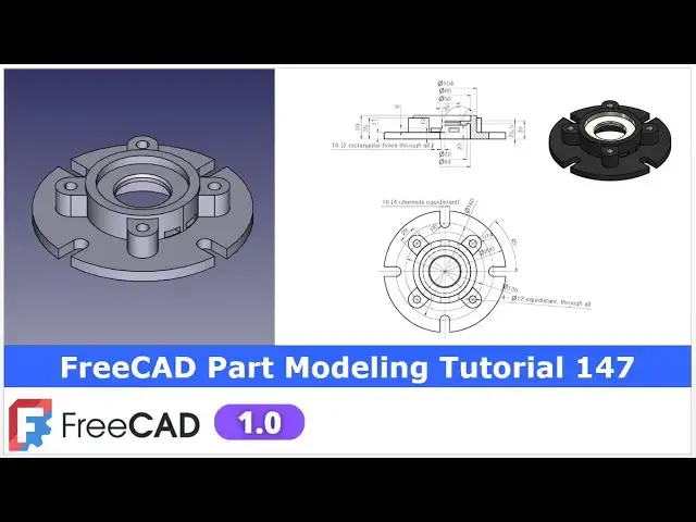
FreeCAD Part Modeling Tutorial 147 | FreeCAD Tutorial | 3D Modeling | Learn FreeCAD | Mechnexus |
Apr 25, 2025
#freecad #freecadtutorial #learnFreeAD
In this video I have explained How to Model Part in FreeCAD with the help of part design Workbench.
▶️ Join my channel membership and keep supporting my work:
https://www.youtube.com/channel/UCcn6z2whMaFu-_LDsEXCfVA/join
▶️ Visit my website for more info on FreeCAD-:
https://mechnexus.com/
▶️ Get my FreeCAD Crash Course for beginner-:
https://www.udemy.com/course/freecad-course-for-beginner/?referralCode=3BA9B526A12F96295D44
▶️ Download Source File of Tutorial-:
https://mechnexus.com/mechnexus-youtube-tutorial-source-file/
▶️ Buy Me a Coffee
I am very grateful that you watch my videos and I am constantly trying to improve the quality of the videos on this channel. If you'd like to help me do this, please consider supporting me so that I can to continue to produce content for your enjoyment.
👉 Help support this channel by buying me a coffee: https://ko-fi.com/mechnexus
Show More Show Less View Video Transcript
0:00
hello friends welcome to Freka tutorial
0:02
and in this tutorial we will model this
0:04
part from the scratch as you can see
0:07
that uh I have already modeled it and uh
0:10
it is matching with a isometric view of
0:13
our reference drawing we will create
0:16
this part from the
0:18
scratch so let's uh start our
0:21
tutorial for this tutorial I am using
0:24
the frecad version 1.0 so you must have
0:28
at least Fread version 1.0 or higher
0:32
version so let's uh start our
0:35
tutorial i will close this file and
0:38
create a new
0:39
file if you want to learn free CAD from
0:43
the scratch then you can buy my complete
0:46
free CAD course from zero to expert this
0:50
course is designed from the scratch to
0:52
the advanced tools and advanced modeling
0:56
in free so here if you visit this course
1:00
page then detailed course description is
1:02
given and what you will learn user will
1:06
be easily to switch from a paid software
1:09
to the opensource freead generating 3D
1:12
model and skillfully design mechanical
1:15
parts master Frecad you will acquire the
1:19
proficiency in a tools function and
1:23
interface and uh you can create a
1:27
complex model in a free and hands-on
1:30
project
1:31
exposure and
1:33
uh if you scroll down you will find the
1:36
course content like in a first sections
1:39
I have a explain the free CAD
1:42
introduction and what is the new feature
1:44
in 1.0 so you can see the lecture inside
1:48
this section second section is to
1:51
getting started with a free CAD 1.0 and
1:54
how you can
1:56
customize and third section is a
1:58
fundamental of a sketching to understand
2:01
the sketching and constraining in free
2:04
CADs
2:06
fourth section is a fundamental of a
2:08
part design where I have a detail
2:11
explain the all essential tools of a
2:14
part modeling then fifth one is
2:18
dedicated to the mechanical part
2:20
modeling and here I have took the
2:23
practical examples of a mechanical part
2:26
like a gear cover offset guide anchor
2:29
bracket bend pipe socket form
2:31
lower lever bracket etc next one is a
2:35
mixed part modeling in Frecad where I
2:39
took the example like a modeling of a
2:41
coffee mug smartphone
2:43
etc next is a working with a freecad
2:46
assembly and here I have explain how to
2:50
create an assembly in freead next
2:52
section is a free CAD drawing where I
2:56
have a explain how to create a technical
3:00
drawings in a free CAD and here I have a
3:03
manufacturing point of view i have
3:05
included the topic like how to create
3:07
part list add welding add surface finish
3:10
symbol how to add the GD&T next one is a
3:14
advanced tutorial in Frecad where I have
3:17
also took the FE analysis in Frecad 3D
3:21
printing and uh how to use
3:24
the Python tools in Frecad next one is a
3:28
productivity enhancement tool in freead
3:31
where I have explained many tools in a
3:34
frecad which will save your time
3:38
and you can create the complex model or
3:43
a complex task within a less span of a
3:46
time by using this productivity
3:49
enhancement tool next section is
3:51
advanced part modeling in freead here I
3:55
have a took the complex example like a
3:58
gearbox housing enclosures and a cover
4:02
shaft covers so these are the complex
4:05
part modeling in a free CAD next one is
4:08
a advanced drafting and detailing in a
4:10
free CAD here I have took the complex
4:14
drawings and I have created the model
4:17
and also created the drawing and these
4:20
are the lengthy tutorials of more than
4:24
30 minutes 40 minutes or 45 minutes and
4:28
uh last one is a projects on a free cat
4:30
where I have took the example of a clamp
4:35
modeling and assembly in a free cat from
4:37
the
4:38
modeling to the assembly
4:41
Everything is included under the project
4:45
on a free CAD modeling to
4:48
assembly so once you buy my course you
4:51
will be redirected to the Google drive
4:54
and here is the my course complete free
4:57
course from zero to expert go inside and
5:02
uh the sections I have shown you on my
5:06
Kofi shop page so exactly same lectures
5:11
under the section is created for example
5:16
section one is a introductions to free
5:19
1.0 and what is new in a freecad 1.0 so
5:23
if you go to the section one so there
5:26
are the 18 lectures and if you go inside
5:29
of the sections one you will find the 18
5:33
lecture total and once you go to the
5:36
lecture one you will find a video file
5:39
which you can download to your system
5:42
and you can watch it so this does not
5:47
require internet connections once you
5:49
downloaded it and uh you can uh learn
5:53
free guide on the
5:56
go and this course is updated on a equal
6:00
interval of a time once the new feature
6:03
is came and uh once you purchase the
6:06
course you have the lifetime access to
6:09
the course and in the case of any doubt
6:13
any query you can mail me at admin
6:16
ratemn
6:17
nexus.com at the end you will find one
6:21
uh video which is a promotional video
6:24
you can watch the video and uh take the
6:27
whole overview of the course you can
6:30
also explore my shop where you can uh
6:33
download the tutorial source file and
6:36
some interesting projects on free CAD
6:40
you can find my course link on my
6:43
YouTube channel you can see the course
6:45
link and uh you can also find my Kofi
6:49
course page link on uh pin comments and
6:53
uh video descriptions so buy my course
6:58
and uh keep supporting my free CAD works
7:00
your small course purchase will uh help
7:04
me to grow this channel and it will also
7:08
motivate me to create more awesome
7:11
content on free cat
7:13
so please check out my course on a free
7:18
CAD from uh 02
7:21
expert and now we will come back to our
7:26
tutorial here I have created a new file
7:29
and uh I will create my body and let's
7:34
uh start our uh first page
7:38
so first on the origin plane and uh
7:41
select this front plane which is exit
7:45
plane and uh click on the sketch and now
7:49
let's uh of the origin plane and uh if
7:53
we read our part so this is the circular
7:57
profile so we will uh create our revolve
8:01
profile so first we will create this
8:04
profile and revolve it to the
8:08
360° so let's first select the polyline
8:12
tool and start creating our
8:15
sketch so I will uh create a rough
8:18
profile and uh
8:21
then we will constrain it
8:39
so if you see the section view so this
8:42
is the approximate profile and now first
8:45
thing we will do we will add a relevant
8:48
relation so first make this
8:52
vertical and uh this one
8:55
horizontal this one
8:58
vertical and now first we will start
9:02
constraining the outer profile so select
9:06
the smart dimension and we will select
9:08
this end point and uh provide the
9:12
dimension so this is the radius of 100
9:15
mm because of our diameter is of 200
9:19
which we can see here and
9:23
now let's uh provide the further
9:27
dimension this point is of
9:36
42 and uh now let's move it
9:43
And let's select this point and this
9:45
point and provide a horizontal
9:49
dimension which is of
9:54
36 and uh let's constrain this
9:59
point horizontal dimension of
10:03
25 and
10:06
now constrain this one select it and uh
10:11
provide it a 4 mm and
10:16
now let's constrain this
10:19
point so this is of a
10:24
25.5 select smart
10:28
dimension
10:31
25.5 and
10:34
Then move
10:38
it and
10:40
let's provide the total
10:43
height select smart
10:45
dimension select this point to this
10:48
point which is of
10:55
39
10:57
and this is of 100
11:00
let's define this
11:06
height which is of 11
11:08
mm and now let's constrain this
11:12
point so to constrain this point we will
11:16
select this point and our origin point
11:19
and add a horizontal
11:21
dimension
11:23
of
11:27
52 and now let's move this
11:32
point and
11:36
let's constrain this
11:38
point select a
11:42
dimension select this one and this one
11:46
and this is of
11:50
42.5 and
11:52
now let's move
11:56
it so here if you see here is a chamfer
12:02
is
12:04
given we can create this chamfer later
12:08
also let's provide this uh angle of the
12:13
chamfer which is of
12:19
30 and now let's uh constrain this
12:23
height select a smart dimension select
12:26
it this point and this point and the
12:31
height is of
12:39
30 and we will also constrain this point
12:43
select this point and this and uh
12:46
provide a vertical dimension of 23
12:52
so our uh profile is fully constrained
12:56
let's uh move the dimension to the
12:59
outside so that you can see the
13:02
dimension very
13:07
clear now move it move it
13:18
so this is the revolve profile and now
13:21
we will revolve it around our axis so
13:25
let's uh exit the
13:28
sketch press zero for isometric
13:31
and let's select the sketch and click on
13:34
the
13:35
revolve so we wanted to revolve around
13:37
the Z axis so we can see that revolution
13:40
is created say okay
13:45
now we will create a next feature with
13:49
respect to our isometric drawing so now
13:52
we will create this pad which we can see
13:56
in top view this four pad so select the
13:59
face and uh click on the
14:01
sketch press
14:03
zero switch to the top view and now here
14:07
we will uh read the dimension so if we
14:09
can see here the PCD is of 130
14:13
select a circle tool and uh we will
14:16
create a
14:17
circle and uh give it a
14:22
130 and uh select it and uh make it
14:27
construction and now here we will also
14:30
project this diameter click on the
14:33
project and project it and let's switch
14:36
to the wireframe
14:38
and
14:40
now we can see here the radius R14 is
14:43
given so here we will
14:46
first create
14:48
a circle or threepoint arc so let's
14:51
create a threepoint
14:52
arc and uh
14:55
this center of arc will be on our
14:58
construction circle so make it a
15:02
coincidence and at the same times
15:05
provide this radius of
15:09
R14 and
15:12
now we will
15:15
uh give the angular constraint so this
15:19
is at the
15:20
center of this 90° so this line is of a
15:24
40° so first thing we will do is to
15:29
create a
15:32
line and make it a
15:35
construction and let's select a smart
15:39
dimension and uh
15:42
provide the angle of
15:45
45 and
15:47
now make this point and this point as a
15:52
coincidence one so here is a
15:55
conflict so we will press Ctrl
15:58
Z and we
16:01
will delete it and let's move it now I
16:06
will select this and this and add a
16:08
coincidence
16:11
relation and
16:14
now we will also create a threepoint arc
16:17
select a threepoint arc and create arc
16:20
on the
16:21
construction and select this and this
16:25
and made it equal and now we will create
16:28
two line by joining these two points on
16:31
both the sides so select a line tool
16:34
select this and
16:36
this this
16:39
and this now select this line and this
16:43
line and add a parallel relation
16:46
similarly select this line and this line
16:48
add a parallel relation and now we will
16:52
add a
16:53
tangency to this and
16:57
this so now this is the our uh first
17:01
profile and our sketch is completely
17:06
closed and let's come out of the
17:10
sketch now here I will uh switch to
17:15
the flat lines now select the sketch
17:20
click on the
17:22
pad and
17:24
uh give
17:26
the pad distance 24 mm say
17:32
okay and
17:34
now we will uh polar pattern it so
17:38
select the pad and click on the polar
17:41
pattern and here we will uh provide the
17:45
quantity
17:47
four say okay so you can see that uh
17:51
this polar pattern is created now switch
17:53
to the isometric and set this top
17:57
view now here we will uh project this
18:01
four arc and uh create our circle so
18:04
let's select the face and click on the
18:08
sketch click on the project
18:10
geometry and we will uh project this
18:13
four
18:14
radius and we will create a four
18:17
holes so select the circle tool and
18:22
create a four circle
18:30
and now select the smart
18:32
dimension and uh
18:35
let's see the four holes which are 12
18:38
equid distance through
18:40
all so provide it at 12 say okay and now
18:47
select control key and select all four
18:50
circles and uh make it equal and say
18:54
close now select the sketch and now
18:57
select the whole wizard
19:00
and here we want uh diameter 12 so
19:04
provide 12 and we can see that four
19:07
holes which are through wall so simply
19:10
give the through walls and say okay so
19:13
here uh you can do one
19:15
thing in this pad you can create a hole
19:18
and you can polar pattern this pad and
19:21
hold at the same times so no issue you
19:25
can also follow the different approach
19:27
which you are comfortable and
19:30
now if you see the top view there is a
19:33
cut so now we will create this cut so
19:36
select the top plane and click on the
19:39
sketch and
19:41
uh let's uh set our model to the right
19:44
orientation and now click on the top
19:46
view and now here we will find out this
19:50
PCD first
19:54
so this is the PCD of
19:57
160 so let's create the
20:03
circle and select it and make it
20:06
construction and select smart
20:09
dimension provide the 160 and
20:13
uh we will
20:17
create threepoint arc select it and uh
20:20
create a threepoint
20:23
arc now select this and this and uh add
20:26
a
20:30
coincidence and
20:33
now select this and this and add a
20:36
coincidence now let's move
20:39
it and we will also project this outer
20:42
diameter select it and uh project it and
20:47
select a threepoint arc and create one
20:51
arc and now select this our newly
20:54
created arc this outer diameter and add
20:57
a tangency now we will create a line
21:01
which will be the vertical so select a
21:04
line
21:06
tool create a line this side and on the
21:11
other
21:12
side now select it make it uh vertical
21:18
select it and make it vertical and now
21:22
select this and this
21:24
tangent select this and this and add a
21:28
tangent and now let's select a smart
21:31
dimension and provide the radius of 8
21:35
mm say
21:36
okay click on
21:39
close and now select the sketch and
21:42
click on the
21:43
pocket and uh say it through wall and
21:47
say
21:48
okay and now we will uh do the same
21:52
procedure to polar pattern it to the
21:56
four quantity which we can see here now
21:59
select it click on the polar
22:02
pattern and here fread automatically
22:05
took this Z axis we have to just define
22:08
the
22:09
quantity so we have created the for
22:14
cut now we will move to the next
22:17
feature which is to create a cut if you
22:22
see here there are the two rectangular
22:24
profile which we can see which are the
22:27
cut so here we can see
22:29
the a note two rectangular holes through
22:34
walls which means that
22:36
uh this is the rectangular cut which is
22:39
the through wall and we can see the
22:40
hidden lines and in isometric view we
22:44
can also see it there are the two cuts
22:47
which are the through wall on the other
22:48
side
22:50
now for this we will uh simply press our
22:53
model to
22:55
the isometric view and we will on the
22:58
origin plane and now if you see the
23:00
orientation so this
23:02
is the cut which will be come on this
23:06
exit plane so select the exit plane and
23:08
click on the sketch and for the better
23:12
sketching I will off the origin plane
23:14
and from here I will switch to the
23:16
wireframe view so that I can draw it so
23:20
first thing is to select a rectangle
23:24
tool and create a rectangle and now
23:27
let's provide a
23:29
dimensions select a smart dimension
23:31
provide it 16
23:35
and uh this is of 6
23:41
mm and uh position from the origin is of
23:45
4
23:49
mm and
23:52
now position from the
23:55
bottom so if you see here the position
23:59
from the bottom is of a 12
24:01
mm which we can see so from here to here
24:06
is of a 12 mm so this is the fully
24:11
constrained sketch and uh let's come out
24:15
of this sketch and create a cut and now
24:19
select a model and uh
24:22
select the sketch and click on the
24:25
pocket
24:27
tool and
24:29
here we will make it a through
24:32
wall and we will make it symmetric to
24:35
the plane so you can see that
24:38
uh back side and front side is a cut is
24:42
created which is the our requirement as
24:45
per the our drawing now this cut which
24:49
we are seeing in a hidden line we will
24:52
simply mirror this cut on the other side
24:55
press
24:56
zero and select this cut and click on
25:00
the mirror
25:03
options and from here select reference
25:06
and select this YZ plane and click on
25:11
okay
25:15
so if you see our uh reference drawing
25:18
isometric view our reference drawing
25:20
isometric view is completely
25:23
matching with uh our freet part so we
25:27
have a successfully converted this uh 2D
25:30
drawing into the 3D model now let's uh
25:33
provide a color like our reference model
25:37
to provide a color select a body and uh
25:40
go to the appearances and in appearances
25:43
we will provide first a black color so
25:46
go to the diffuse color and uh we can
25:49
also adjust the color by dragging this
25:53
uh small
25:54
triangle
25:56
so let's give the approximate color with
25:59
respect to our reference and click on
26:02
okay and click on
26:04
close now we wanted to give the
26:08
individual faces different color so for
26:11
this we will switch to the part
26:13
workbench and here is the options so I
26:16
will uh select the these two
26:20
faces but first select a single phase
26:23
and on this and then we will add the
26:27
multiple faces by pressing the control
26:30
key and here this uh bore is of a
26:33
different
26:35
color so select the
26:38
faces
26:41
and go to the custom appearances go to
26:44
the diffuse color and now here we will
26:48
uh provide a white color simply select
26:52
white and say okay and say
26:55
close and we will
26:57
also make it okay so you can see that uh
27:01
we have successfully modeled this part
27:04
from the scratch with the help of uh
27:07
part design
27:09
workbench this is all about this
27:11
tutorial thank you for watching and
27:13
thank you for your valuable time
27:16
[Music]
#CAD & CAM
#Training & Certification
#Computer Education