live_tv
Livestream Starting Soon
00
Hours
:
00
Minutes
:
00
Seconds
Up next in 10

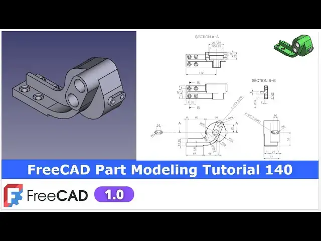
FreeCAD Part Modeling Tutorial 140 | FreeCAD Tutorial | 3D Modeling | Learn FreeCAD |
Apr 24, 2025
#freecad #freecadtutorial #FreeCADforbeginners
In this video I have explained How to Model Part in FreeCAD with the help of part design Workbench.
▶️ Join my channel membership and keep supporting my work:
https://www.youtube.com/channel/UCcn6z2whMaFu-_LDsEXCfVA/join
▶️ Visit my website for more info on FreeCAD-:
https://mechnexus.com/
▶️ Get my FreeCAD Crash Course for beginner-:
https://www.udemy.com/course/freecad-course-for-beginner/?referralCode=3BA9B526A12F96295D44
▶️ Download Source File of Tutorial-:
https://mechnexus.com/mechnexus-youtube-tutorial-source-file/
▶️ Buy Me a Coffee
I am very grateful that you watch my videos and I am constantly trying to improve the quality of the videos on this channel. If you'd like to help me do this, please consider supporting me so that I can to continue to produce content for your enjoyment.
👉 Help support this channel by buying me a coffee: https://ko-fi.com/mechnexus
Show More Show Less View Video Transcript
0:00
hello friends welcome to Fria tutorial and in this tutorial we will model this part as you can see that uh I have
0:08
already modeled it and it is matching with the isometric view of our uh
0:14
reference drawing so we will read all the dimensions of this orthographic view
0:21
front top side and sections and we will model this part from the scratch so for
0:28
this tutorial I am using Frecad version 1.0 so you must
0:34
have at least 1.0 or higher version of a free CAD now I will close this file and
0:41
create a new file
0:46
you can also visit my website macexus.com where I write articles and
0:52
tutorials on a free CAD and you can also access my 3D part library of a free CAD
1:01
you can download the part from here and you can use in your projects with
1:07
modifications you can also access my 2D drawing
1:13
library where you can uh download this 2D drawings and uh you can create 3D
1:21
models with respect to these drawings you can also support me on
1:29
coffi.com you can buy me a cup of coffee your small support will uh help this
1:35
channels to grow and uh it will motivate me to create more awesome content on uh
1:42
free CAD you can find my Kofi donation page link in a video description as well
1:49
as you can also see my Kofi page URL on this
1:54
header so let's come back to our tutorial now here I have created a new
2:00
file and part design workbench is active and now I will create the body and I
2:06
will on my origin plane and now we will uh read our model and we will create our
2:13
first sketch so if you see our isometric view so we will first create this
2:21
profile on a front plane whose detail we can get here
2:27
now let's uh select the front plane and click on the
2:33
sketch and now go to the model tab and hide the origin plane
2:39
now here first we will create a
2:44
circle and uh I will make this circle as a construction circle and
2:51
uh give the dimension of uh
2:57
72 because the radius is 36 so I'm creating a diameter and
3:05
now this is the our origin which we have created here and now we will uh create
3:12
one construction circle at approximate location here for
3:17
this so click on the circle and uh also make this
3:24
circle as a construction one and now let's give the dimension so we can see
3:30
here the 29 dimension from the origin so select smart dimension
3:38
and provide the 29 and now from this axis to this center is of
3:47
12 mm which we can see here and now let's
3:52
uh move the dimensions so this is the construction geometry and uh let's
3:59
also fix this uh diameter which is a construction one
4:05
so we can give the roughly 19
4:11
mm and
4:20
now now let's uh create a threepoint arc and then create a two lines and then
4:28
we will create this arc so here go select a threepoint arc select this
4:34
point this point and uh here make the center coincidence and
4:42
now we will create an approximate threepoint
4:47
arc and uh whose center will be coincidence to this uh construction one
4:53
and add a coincidence and uh this radius is of R14 so we will select radial
5:01
constraint and provide it R14 and now we will
5:08
uh join this two points with a line so select the line
5:16
tool and join it select the line tool and join
5:21
this and now we will move this line and we will also move this
5:31
line and move this arc so first let's uh add a
5:37
tangency between this arc and line and uh same way add a tangency here
5:45
say tangent say here say
5:50
tangent and now we can see that uh our sketch is
5:55
fully constrained so we will come out of the sketch now we will create a pad of 34
6:08
mm select the sketch click on the pad and uh give the 34 mm and say
6:16
okay now let's move to the next feature so if we see the front view so we have
6:24
created this face and now on this face
6:30
we will create this slotted like cut so let's select the face and click
6:36
on the sketch and click on the project geometry and uh project this radius and now we will
6:45
select a slot tool select this point and this
6:50
point and now we will make this arc and this arc
6:57
as equal which we can see in the image now our slot is fully constrained and
7:03
now we will create a pad of 21 mm so select the sketch click on the pad and
7:10
uh say 21 mm and say okay and
7:16
now let's switch to the isometric view and now here we will create this
7:23
profile so press
7:30
zero and uh here we will refer this front view so we
7:37
will select this face and uh create a sketch and now click on the project
7:43
geometry and project this uh arc and also project this radius and now
7:52
here we will create one rectangle and we will delete this
8:00
line and uh this is of 8.6 mm so we will select a smart
8:07
dimension and uh provide it 8.6
8:14
six and now we will uh provide the
8:20
distance 64 mm and
8:27
now we can add a vertical relation here between these two points
8:36
and now we will create threepoint arc
8:43
here select and uh create a threepoint arc and make this and this as
8:52
equal and now let's fix this point with the origin
9:01
and uh give the horizontal dimension of 122
9:07
you can check this dimension by adding this and
9:12
now I will uh select a threepoint
9:18
arc and uh select this point and create a threepoint arc and now here I will uh
9:27
select this line and arc and add a tangent select this line and arc and add a tangent
9:34
and now here we will see what is
9:42
unconstrained so this is the unconstrained because we have not fixed
9:48
this line so from the center we will uh give
9:53
the dimension of 38 select smart dimension select it and uh give the
10:01
38 and now let's see what it done
10:06
constraint so here if you see here tangency is added so we will
10:15
make this uh coincidence now this will be in a equal
10:26
proportion and now if you see
10:33
here here is a 12 mm is given and this this is the tangent with this line
10:40
so here I will select this and this and add a tangency so you can see that
10:49
uh it is a perfectly tangent and if we join this
10:56
line we can get the tangency now let's uh close the sketch
11:02
and uh we will create and extrusion now
11:08
here we will learn how we can offset the extrude in uh two dimensions
11:17
if you see here so here is a step of a 2 mm
11:23
so we will uh click on the pad and from here we will select the two
11:29
dimensions and first dimension we will give the
11:36
48 and we will set it
11:45
reverse so first let's make adjust the dimensions and uh say reverse so now you
11:52
can see that uh in one direction it is created now add a two dimensions and here I want 2
12:00
mm offset so here I will provide
12:06
minus2 so here if you see our sketch is
12:11
uh on this face if you go this pad and uh if you see this is the minus2
12:19
distance which we have given in a two
12:25
directions so this is how we can create extrusion offset to the sketch now we
12:33
will off it and uh let's move to the front view so here we
12:42
have to add the material here so we will select the face and click on the sketch
12:48
and uh we will uh project this horizontal and vertical click on the project
12:54
geometry and select a rectangle tool and add a rectangle and
13:01
now the thickness is of
13:07
3.4 you will uh minus this uh 8.6 from you will get it and now horizontal
13:14
distance is of uh 64 and now here we can do one more thing
13:21
as in our previous sketch we have given this distance 64 so instead of giving
13:27
dimensions I can add a coincidence constraint so so that once the this 64
13:32
distance of a pad change then it will automatically get updated now close it
13:38
and we will add the material and we will define this end
13:44
face so select the sketch and click on the pad say reverse from here select up to
13:52
face and uh select this face now say
13:59
okay say zero for isometric and now we will uh create our next feature
14:07
so let's uh move to the isometric view now we will create this feature and for
14:12
this we will uh create the sketch on this face so let's create a sketch
14:18
select this face and click on the sketch and now let's uh rotate our model
14:26
and let's project this geometry required geometry so click on the project
14:32
geometry project this age this arc this arc and this
14:39
age now let's switch to the front view and from here we will switch to the
14:46
wireframe and now we will create our profile select
14:52
line tool select this and this and uh let's select a threepoint arc select
15:00
this and uh this and uh set it
15:07
equal and now we will select a line
15:15
tool and now let's also project this radius so click on the project
15:22
geometry and move to the front plane and here we will uh create
15:31
arc so basically we are trying to create this profile so let's uh select a threepoint
15:39
dark and uh select this and this and let's add a
15:50
tangency set to the front view and now let's uh create threepoint arc here
16:02
and now let's uh select this and this and uh say
16:08
tangent and now we will uh make this point
16:16
coincidence on this axis and now let's uh create a
16:21
threepoint arc of R22 so we will select a threepoint arc select this and this
16:28
and uh let's add a tangency and now move this
16:35
arc and uh create a horizontal
16:42
line and project this edge select a line tool
16:50
create a vertical line and
16:56
also make this vertical and uh this is of
17:04
a 6 mm from the age so we will select it
17:11
and give the 6 mm and this is the height is of a 16 mm
17:18
so we will provide a height of 16 mm now move this 6 mm and 16
17:27
mm and now let's add a tangency
17:33
here so till here our sketch is fully constrained
17:38
now we will again project this geometry and uh select a threepoint arc
17:45
select this point this point and here let's select this
17:51
and this and add a tangency and now create one more arc and
17:58
close our profile so select a threepoint arc select this let's first make this
18:05
normal and uh and then add a
18:14
tangency so here let's see what is
18:27
unconstrained let's press Ctrl
18:33
Z okay now let's uh select this and this and uh made it equal and now here is a
18:42
coincidence issue so select this and this and add a coincidence so our uh
18:49
sketch is uh fully constrained which we can see now we will come out of it and uh
18:58
create a pad of 6 mm so let's switch to the flat lines
19:04
view and select the sketch and click on the
19:10
pad and uh give the thickness 6 mm say
19:17
okay and now we will go to the isometric view now
19:24
we wanted to create this profile and uh for this we require a data plane so we
19:31
will on our origin plane and uh here we see the dimension
19:36
80 so we will create a datam plane at a distance of 40 mm with respect to the y
19:44
z plane so select the plane and uh click on the datam plane and in a z directions
19:50
give the 40 mm and uh say okay
19:55
now let's off the origin plane and rebuild our datam plane and now we will
20:02
select our datam plane and click on the sketch and now here we will uh create a
20:10
slot profile on the axis
20:16
and now instead of this axis we will
20:25
uh give the dimension 51 and let's check if it is on the axis it is 51 then
20:33
okay so I will project this age and uh let's say smart
20:42
dimension so it is a it is coming 50 mm
20:47
so it is not on the axis so we will edit our sketch
20:56
and delete this slot and here we will create a same slot
21:03
but not on the axis and let's make uh this and this
21:11
horizontal and now from the bottom let's uh give the 51
21:21
mm and uh slot center to center distance is of 16 so let's select this center
21:28
point and this and give the 16 so let's close this
21:33
report view and
21:39
now and if you see here so this is the tangent to the
21:44
H so this axis is here so we will provide the tangency and this radius is
21:51
of R six so we will select it and uh let's hide this report
22:00
view sometime this report view is very annoying so you can drag it something at
22:06
the bottom now close it now here we will off the data plane
22:13
select the sketch and uh click on the pad and uh we will select uh up to face
22:22
and we will select this face and say
22:28
okay now if we see this front view so we can
22:33
see that uh this is the mirror on the other side so we will select the pad and
22:38
uh click on the mirror say
22:44
mirror and uh here we will uh select our reference which is uh y z plane and say
22:54
okay so you can see that our feature is a mirror on the other
23:00
side now if you see the isometric view we can uh see these two holes and now we
23:07
will select this face and uh click on the
23:13
sketch and now let's uh press zero for isometric view to create this hole we
23:20
will project this two arc click on the project geometry and uh project it so
23:26
that we get a center points and now let's uh create a hole so if you see
23:34
the side view so this is the two hole of 6.3 so I will select a circle and uh
23:42
create two circle and uh select a smart dimension
23:50
give it a 6.3 and select this and this and uh make
23:55
it equal now close it now select the sketch click on the
24:01
cut and uh say it through all say okay
24:15
now we will uh create these four counterbore holes whose position we can
24:21
uh see here in a top view so I will uh select this top face and uh click on the
24:30
sketch press zero and set the top view and now here
24:35
first uh I will uh create a rectangle and uh make it a
24:44
construction and now here we will provide the
24:50
position so that uh we can project this uh horizontal and vertical line and uh
24:57
from the age it is of a 12 mm give the 12 mm and uh from this edge it
25:05
is of a 10 mm and uh from the center it is a 14 14
25:11
28 so I will provide this 28 and
25:18
now provide this which is of 25 so here what I have did I have first created a
25:26
position of my holes now I will create a four circle at four points and let's see
25:33
the counterboard's detail so counterboard we can see that D 8 is through and this is a diameter 14 with a
25:41
2 mm depth so here we will create a four circle of diameter 8 so we will select
25:47
the circle tool create four
25:54
circle and select a smart dimension and give it 8
26:01
mm and now we will uh select all
26:07
four and uh made it equal and now here we can see that
26:14
uh center is offset so make it a coincidence so our uh sketch is fully
26:20
constrained now we will close it and now we will uh create this counter board
26:27
with the whole wizard and now here our uh drill is of 8
26:33
mm so here I will provide the 8 mm and uh this will be the through wall we can
26:39
say and uh in a whole cut type we will select a counter board so our counter
26:46
board is of 14 and depth is of 2
26:51
mm so you can see that a counterboard hole is created set
26:58
okay and now if you see the back side which is
27:04
not visible in isometric so we will refer the orthographic view so here in a
27:09
section view we can see the cut so we will select the backside
27:15
face and uh click on the sketch and we will uh project this radius press zero
27:23
for isometric and rotate our model and now here we will uh create a
27:30
circle and uh select a smart dimension and uh provide it
27:38
57.19 and uh this is of a 12 mm depth say close select the sketch click on the
27:47
cut and provide the 12 mm now there is a one more cut so we
27:56
will select the face and uh click on the sketch select a circle and uh create a
28:03
circle and this is about 50.82
28:12
click on close and uh this is we will subtract
28:18
it 28 - 12 so we will select the sketch click on the
28:26
cut so here I will give the 28 - 12 directly so that it will automatically
28:33
calculate it and say okay now press zero
28:42
now let's see the minor details so here uh our model is uh
28:49
completed and uh you can see that we have successfully model our
28:56
part from the scratch by reading the autographic view and our model is
29:03
matching with the isometric view now we can uh give the colors so if
29:09
select the body and go to the appearances and from here click on the custom appearances and uh select this
29:17
and uh let's uh select approximate color
29:23
and say okay say close
29:31
now we wanted to give the separate color to this face so select the face and uh
29:36
switch to the part workbench and in a part workbench you
29:42
will see one options let's uh move it so here you
29:48
will see the option of uh color per face select it so here you will see that face is
29:56
selected and now click on the custom appearances select the face custom appearances and instead of green I will
30:04
provide the white color and say close so you can see that uh our free
30:12
model is a exact replica of uh our uh reference drawing isometric view so
30:20
this show the capability and power of a free cat that uh it is a same capable as other CAD software
30:29
available in the market so this is all about this tutorial thank you for
30:34
watching and thank you for your valuable time
#CAD & CAM
#Sculpture
#Educational Software
#Computer Education