live_tv
Livestream Starting Soon
00
Hours
:
00
Minutes
:
00
Seconds
Up next in 10

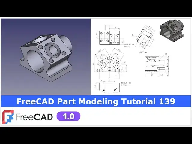
FreeCAD Part Modeling Tutorial 139 | FreeCAD Tutorial | 3D Modeling Tutorial | FreeCAD Community |
Apr 24, 2025
#freecad #freecadtutorial #FreeCADforbeginners
In this video I have explained How to Model Part in FreeCAD with the help of part design Workbench.
▶️ Join my channel membership and keep supporting my work:
https://www.youtube.com/channel/UCcn6z2whMaFu-_LDsEXCfVA/join
▶️ Visit my website for more info on FreeCAD-:
https://mechnexus.com/
▶️ Get my FreeCAD Crash Course for beginner-:
https://www.udemy.com/course/freecad-course-for-beginner/?referralCode=3BA9B526A12F96295D44
▶️ Download Source File of Tutorial-:
https://mechnexus.com/mechnexus-youtube-tutorial-source-file/
▶️ Buy Me a Coffee
I am very grateful that you watch my videos and I am constantly trying to improve the quality of the videos on this channel. If you'd like to help me do this, please consider supporting me so that I can to continue to produce content for your enjoyment.
👉 Help support this channel by buying me a coffee: https://ko-fi.com/mechnexus
Show More Show Less View Video Transcript
0:00
hello friends welcome to Fria tutorial and uh in this tutorial we will model this part and uh we will do it with a
0:09
part design workbench and uh you can see that uh I have already did it and the
0:16
isometric view is matching with our frecad model we will read the dimensions
0:24
of orthographic view and we will create this part from the scratch so for this
0:30
tutorial I'm uh using the Frecad version 1.0 so you must have at least Frecad
0:37
version 1.0 or higher version for this tutorial i will close this file and
0:43
create a new file and I will show you from the scratch you can also visit my
0:48
website macexus.com where I write articles and tutorials on a free CAD and you can also
0:56
access my 3D part library of a free CAD
1:01
you can download the part from here and you can use in your projects with
1:07
modifications you can also access my 2D drawing
1:13
library where you can uh download this 2D drawings and uh you can create 3D
1:21
models with respect to these drawings you can also support me on
1:29
coffi.com you can buy me a cup of coffee your small support will uh help this
1:35
channels to grow and it will motivate me to create more awesome content on uh
1:42
free cat you can find my Kofi donation page link in a video description as well
1:49
as you can also see my Kofi page URL on this
1:54
header so let's come back to our tutorial
2:00
so here I have created a new file and uh I have activated the part design
2:06
workbench and here I will insert my body and on the origin plane and now we will
2:14
uh create our first sketch on the front plane which is a
2:19
exit plane so select the exit plane and click on the sketch and uh hide the
2:26
origin plane now we will uh read the dimensions so if
2:33
you see the isometric view so first we will create this front
2:38
profile and then we will uh extrude it
2:43
so for the dimension we will uh refer this front view and let's create our
2:50
first sketch let's uh create this horizontal edge and uh
2:59
then make this symmetric click on the symmetricity select this point this
3:06
point and this axis and uh here it is of 22
3:13
mm select the line and add a dimensions
3:19
22 and now we will select a polyline tool and
3:25
we will create a rough profile so select a polyline option
3:32
here and uh let's uh create approximate
3:48
profile so here if you see we have created a rough profile and
3:55
we will add some constraint like uh this line we will make it
4:01
horizontal and uh here we will create a two
4:06
fillet here and uh here and uh we will create one
4:13
construction line which will be the coincidence with
4:20
the this point select the line and uh make it
4:27
construction select it and uh make it coincidence and
4:33
now select a smart dimension select this point and define the total height which
4:41
is of 17 mm and
4:47
now let's create angle which is of a 30° on both the
4:56
side and now here we will uh link the
5:03
dimensions which we can do let's uh select this dimension here is a name so
5:10
here I will give the this dimension a name so this is a angle so I will give a
5:18
a for angle and value is of 30 and I will say okay and now I will
5:26
select a smart dimension and give the dimension here
5:31
and now here you will see the equation icon and here we will link the
5:39
dimensions so to link the dimensions we will uh click on it and here you will
5:45
see the equations click on it and type here constraints so here you will see
5:51
the constraint dot A30 because we have given the name so it
5:58
is already showing here and you can see that constraint do a30 here is a 30° got
6:05
linked and say okay now this is the link dimension so if I change this dimension
6:12
this dimension will change so if I make it 35 so you can see that this is the 35
6:20
so this is the parametric once I change this dimension this will change and now
6:25
let's uh make it 30 so you can see that it is changing now let's add align
6:33
dimension of 12.7 so here we will give the one
6:39
dimensions to this which is uh 12.7 and now we will uh link this
6:48
dimension with the 12.7 so here I will click on the dimensions and here I will
6:54
give the d for dimensions and here I will give directly
7:00
127 so here we cannot give the decimal so here I given the dimension
7:07
127 and uh now I will click on the next dimension go to the equation and go to
7:14
the constraints so here D
7:20
127 say okay so now you can see that uh
7:26
this dimension is also link now if I make it a 15 so you can see that it is
7:33
changing to the 15 and now make it a
7:38
12.7 which is a required dimension and
7:44
now if you see here the total height is given of uh 3
7:50
mm so select a smart dimension and uh provide the value 3 mm and now select
7:59
uh this point this point and provide the horizontal
8:05
dimensions and uh here we can see that this is R2 so I
8:11
will select uh radius and from here I will select the radius constraint and provide 2
8:18
mm and uh here I will select this radius and this radius and made it equal and
8:26
now here is a 5 mm is the dimensions so
8:32
let's constrain this radius now I will select this point and this point
8:40
so this is already 5 mm so we will make it as a
8:45
reference and now if you see this uh radius so we will
8:54
uh make this point this radial point symmetric and we will add a dimension of
9:01
20 mm so click on the symmetricity select this
9:07
radius point and this and this axis and now select the smart
9:14
dimension select this point and this point and give the value 20 so now our
9:22
uh sketch is fully constrained and now we will uh extrude it
9:30
press zero for isometric and select the sketch click on the pad and
9:38
here provide the 15 mm dimension which is shown here and uh
9:46
keep it symmetric to the plane and say okay now the we have created the first
9:53
solid features let's save our part
10:03
and uh let's uh move to the next
10:08
feature our next feature is to create a solid if you see here the back
10:16
side now we will rotate our model and select this back face and click on the
10:22
sketch and let's press zero for isometric and rotate our model and uh
10:28
click on the rear and rotate the cube so this is the right orientation if you
10:34
see now we will uh create a circle of
10:39
diameter 9.5 which we can see here and uh then we
10:44
will uh extrude it now let's uh select a circle tool and
10:52
create a circle here and select a smart dimension and uh provide it a
11:01
7.5 and say diameter 9.5 and say okay and now we
11:09
will create a pad of 6.5 mm select the sketch and click on the pad
11:16
give it a 6.5 and say okay press zero and now let's uh create
11:23
a next feature next feature if we see the section view so here is a revolve
11:31
cut around this axis which we can also see the hollow
11:36
portion in our isometric view and we will on this origin plane and we will
11:42
create this revolve cut on a YZ plane and uh select sketch now we will uh hide
11:52
the origin plane and we will switch to the wireframe view so that uh we do not feel any difficulty in sketching so here
12:02
first uh I will project this diameter so click on the project geometry and select
12:08
it and now we will uh create a
12:17
line horizontal line and uh let's
12:25
uh make it coincidence with this our projected
12:31
line and now let's uh project this edge
12:39
click on the project let's also project this and uh
12:44
we will do the same thing and add here the coincidence constraint now this line is a
12:51
coincidence and uh free to move so
12:57
here we will uh constrain this line with this point so we can see here this uh
13:05
diameter of 9.5 so I will select a smart dimension select this point and this
13:12
point and I will give the 9.5id by
13:17
two you can also create a point here midpoint but I have a constraint it with
13:24
the dimension now uh we will use the polyline tool to create a rough profile
13:30
and then we will constrain it so here is a polyline tool option and uh we will
13:36
create a rough profile for our
13:43
cut and then we will constrain
13:48
it so now select a smart
13:54
dimension select this line and provide the dimension of 6.25
14:00
25 this uh horizontal dimension of 13
14:06
mm and uh this vertical
14:12
line is of 3 mm so we can see that our uh groove
14:19
profile is a fully constraint now we will close it and here we will select
14:25
our sketch and click on this uh groove which you can also say the revol cut and
14:32
from here we will select reference because we we do not want to create a
14:41
revol cut around the standard X Y and Z axis we will define this line as our
14:47
axis so you must select here the select reference option and select this line so
14:54
you can see that uh uh revolve cut is created now say okay now we will move to
15:02
the next feature which is to create a cut in this
15:08
portion and uh whose dimension we can see here
15:15
press zero for isometric and select this plane and uh click on the
15:22
sketch and press zero for right orientation so now if you see
15:29
here it is a 6.5 from the age
15:35
so we will first create a rough circle and then let's uh first constrain
15:43
this circle which is of uh 9 mm and
15:49
now from the age to the center is of 6.5 so we will click on the project geometry
15:56
and uh select a smart dimension and uh provide it a
16:05
6.5 and now we will also project this age
16:11
and provide the position from this age and select this center and uh this is of
16:19
6.35 five you can check the dimensions from
16:26
the drawing here and uh now our sketch is fully constrained we
16:34
will close it and uh create a cut select the sketch click on the cut
16:42
so here we will provide approximate value here so that
16:49
uh cut get open in this free area so
16:54
let's provide the 10 mm so for the 10 mm here it is
17:01
a removing the material here so we will give the 8
17:07
mm so this looks fine or let's try with the up to phase
17:14
and select this phase so that is much better you can do both
17:22
the things but uh here I will uh keep it 8 mm you can also select up to phase as
17:29
I shown you and now let's uh create a next features next feature is uh to
17:36
create this four holes which we can also see in isometric here we will select the
17:43
same face and uh click on the sketch and let's press the
17:49
zero and here we will uh project this diameter
17:55
because our position of the hole with respect to this cut
18:00
diameter so here I will first select a twopoint rectangle and create a
18:07
rectangle and now I will move this line and here I
18:14
will provide a tangency select this line and make it tangent select this and uh make it
18:23
tangent let's also select this and uh make it tangent and now
18:29
here we want this uh rectangle as a construction geometry because we will
18:37
place our hole at the four corners now also select this and add a
18:44
tangent now we will create a four holes and u this is of diameter 2 mm so we
18:53
will create a four circle at four points of a
19:02
rectangle and now let's select a smart dimensions and uh provide this 2 mm and
19:09
now here we will uh save our time rather
19:14
than giving dimensions to the each hole we will use the equal constraint and now say okay so now if we
19:23
see our drawing so we can see that these holes are a tapped
19:28
hole of a depth 3 mm and these are the hole of M2 which we can see
19:35
here and now this is at eight places and which we can see four on the one side
19:42
and four on the other side so here in our sketch we have uh created the whole
19:49
of diameter 2 and now we will select the sketch and uh
19:55
click on the whole wizard and here we will go here isometric regular
20:04
profile and from drop-down we will select our thread size which is of M2
20:09
and uh depth of the tapping is of 3 mm so make it 3 mm and here if we go so
20:19
this is the class 6H so click on the threaded and from here click on the
20:28
6H and here if we can see here we can find
20:33
the peach option as well but I would uh say use the default one so m2 depth
20:40
three and uh threaded class uh 6H and here we can also define the depth here
20:49
is uh automatically took the 3 mm and uh if you click on the model
20:54
thread then uh update thread view so it will
21:00
uh you know uh show the thread to this hole but uh this uh takes the time of
21:10
computing so if you have a system resource issue your system configuration
21:15
is low then do not use it but for the tutorial I am saying it okay
21:23
and now let's uh move to the next feature which is a same thing to create a hole on the other
21:34
side so we will use the face of the other side and uh click on the sketch
21:41
and we will read the dimensions let's press uh zero for
21:47
isometric and we will create a circle first let's
21:52
uh create a circle and uh click on the project geometry and project this edge
21:58
and this edge and uh from this age it is a 6.5 so we will select a smart
22:05
dimension and uh make it 6.5 and uh this is of a diameter
22:14
9 and uh now the position from the center to the edge is
22:23
of a 6.35 let's uh give it
22:29
a 6.35 so our sketch is fully constrained
22:35
so let's come out of it and now we will create a same cut with a depth of 8 mm which we
22:44
have used for this
22:51
diameter so here so here the problem is the threaded
23:00
feature which I have on so because of this some problem is uh happening so
23:09
let's try again say cut or we will disable this thread view
23:17
from the whole wizard and we will keep it as a so let's
23:25
uh edit this whole wizard and here disable the model
23:32
thread and uh say okay so you can see that thread is got off now let's try
23:37
this cut okay so now here I will give the
23:44
depth of 8 mm and uh you can also select up to
23:50
phase so if you are facing any difficulty to show the thread of the
23:56
hole then my advice is that if it is not necessary then off the thread now let's
24:04
uh create the hole of m2 with a depth of 3 mm as we have
24:10
created on the other side so we will uh select the phase and click on the sketch
24:16
and let's press zero for isometric and uh uh we will first project this
24:22
diameter and uh here I will create a
24:27
rectangle and uh let's uh move the edge and we will uh
24:33
make all four edges tangent to the circle so make it a tangent
24:40
select it and uh make it tangent select it and uh make it tangent select and uh make it tangent
24:49
now here this rectangle is for the
24:55
construction purpose so that I can place the diameter two holes at four corners
25:03
now let's uh create a circle and create a four circle at uh four
25:16
points and let's uh constrain one of the circle so select a smart dimension and
25:23
uh provide this 2 mm and uh press control key select all the diameters and
25:31
uh made it equal now click on close we will select the sketch click on
25:38
the whole wizard and now here I will select
25:45
isometric uh profile and from here select
25:51
M2 depth is of 3
25:57
mm and
26:05
uh say okay so now here if you see so this hole is look uh
26:13
smaller so let's check uh size of this hole
26:18
so here is a isometric regular profile M2 that's okay and let's select uh this
26:34
hole so clearance is
26:39
standard so here if you see this diameter is of 1.2
26:46
two means it is a 2.4 radius and let's select this one this is
26:54
of8 so there is something wrong with this uh
27:02
hole set none and then again select isometric regular
27:08
profile and select uh M2 and uh say
27:17
okay and uh press spacear and on the features so sometimes uh fread uh fail
27:26
to recomputee so now this uh holes which were not looking similar now looking
27:34
fine now let's uh moves to the next
27:40
feature which is we can see the threaded hole at the bottom face
27:48
whose detail is given here and the position is also given so we will select
27:53
the bottom face and uh click on the sketch and
28:01
now we will create a two circle select uh and uh create a circle
28:08
and uh select a smart dimension and define it uh 2 mm and select it this and
28:16
this and made it equal and now this is of a five and 12 so we will project this
28:22
horizontal and vertical edge click on the project geometry select a smart
28:32
dimension give it a five and uh from this to this is of uh 12 and this is of
28:41
already 7.5 so we will uh close it and uh we will use the whole wizard
28:51
tool and we will go to the isometric regular give it a
28:59
M2 define the depth for 3 mm and uh let's leave the class and say
29:08
okay
29:14
now this completes our model let's uh switch to the isometric
29:20
view so you can see that uh we have successfully modeled this part from the
29:30
scratch with the help of a part design workbench and now
29:37
here we can uh see the material so let's uh cross check our model again so we can
29:46
figure out that uh if uh anything happens wrong so this first feature is
29:51
looks okay then select the pad so pad is okay then
29:57
groove so groove is uh also okay now go
30:02
to the pocket so p pocket is also fine then
30:08
hole this looks good so here if you
30:16
see the something wrong is happening
30:22
here so we will go to this pocket and let's select up to the face
30:29
and select this face so sometimes uh freet solvers
30:38
creates a problem let's say
30:44
okay even this doesn't matter because 8 mm depth work for this cut but uh there
30:51
are some glitches with the freet solver so here I have defined it up to face now
30:57
on the hole so we have created the hole and
31:02
there is a hole on the bottom side so if you face any problem then now go
31:09
one by one as I have did to cross check the model so this completes our model
31:16
and uh this is all about this tutorial how to model this part from the scratch
31:22
with the help of part design workbench thank you for watching and thank you for
31:27
your valuable time
#CAD & CAM