live_tv
Livestream Starting Soon
00
Hours
:
00
Minutes
:
00
Seconds
Up next in 10

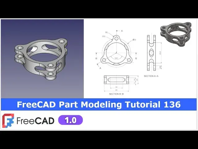
FreeCAD Part Modeling Tutorial 136 | FreeCAD Tutorial | 3D Modeling Tutorial | FreeCAD Community
Apr 24, 2025
#freecad #freecadtutorial #FreeCADforbeginners
In this video I have explained How to Model Part in FreeCAD with the help of part design Workbench.
▶️ Join my channel membership and keep supporting my work:
https://www.youtube.com/channel/UCcn6z2whMaFu-_LDsEXCfVA/join
▶️ Visit my website for more info on FreeCAD-:
https://mechnexus.com/
▶️ Get my FreeCAD Crash Course for beginner-:
https://www.udemy.com/course/freecad-course-for-beginner/?referralCode=3BA9B526A12F96295D44
▶️ Download Source File of Tutorial-:
https://mechnexus.com/mechnexus-youtube-tutorial-source-file/
▶️ Buy Me a Coffee
I am very grateful that you watch my videos and I am constantly trying to improve the quality of the videos on this channel. If you'd like to help me do this, please consider supporting me so that I can to continue to produce content for your enjoyment.
👉 Help support this channel by buying me a coffee: https://ko-fi.com/mechnexus
Show More Show Less View Video Transcript
0:00
hello friends welcome to free tutorial
0:02
and in this tutorial we will uh model
0:04
this part and you can see that uh I have
0:08
already modeled it and our freet model
0:11
is matching with our reference drawing
0:14
isometric
0:15
view i will show you from the scratch
0:18
how you can model this part with reading
0:22
of dimensions of a front top and side
0:25
view of this uh drawing so for this
0:29
tutorial I am using the frecat version
0:32
1.0 so you must have at least Frecad
0:35
version 1.0 or higher version i will
0:39
close this file and uh create a new file
0:43
you can also visit my website
0:46
macexus.com where I write articles and
0:49
tutorials on a freecad and you can also
0:53
access my 3D part library of a free CAD
0:58
you can download the part from here and
1:01
you can use in your projects with
1:04
modifications
1:06
you can also access my 2D drawing
1:10
library where you can uh download this
1:13
2D drawings and uh you can create 3D
1:18
models with respect to these
1:21
drawings you can also support me on
1:26
coffi.com you can buy me a cup of coffee
1:30
your small support will uh help this
1:32
channels to grow and it will motivate me
1:36
to create more awesome content on uh
1:39
free cat you can find my Kofi donation
1:42
page link in a video description as well
1:46
as you can also see my Kofi page URL on
1:49
this
1:51
header so let's come back to our
1:54
tutorial
1:57
now here I have created a new file and I
2:00
have activated the part design workbench
2:02
and first thing which I will do is to
2:04
create a body and then I will on the
2:08
origin plane
2:11
now we will create our first
2:14
sketch which will be
2:17
to create this inner and outer diameter
2:21
on a top plane so we will select this XY
2:25
plane and click on the
2:30
sketch and from here I will off the
2:33
origin plane and here we will create
2:36
internal and then outer diameter so
2:40
internal diameter is of a 50 and outer
2:42
diameter is of a 60
2:46
so let's uh select a circle tool and uh
2:50
create a two
2:52
circles and uh select a smart dimension
2:55
and
2:56
uh provide the outer diameter 60 and uh
3:02
inner
3:05
diameter
3:07
50 now our sketch is fully constrained
3:12
and now we will come out of it
3:17
now we will create a extrusion of 20 mm
3:20
which we can see here so select the
3:22
sketch and uh click on the extrusion and
3:26
provide
3:28
the distance 20 mm and say
3:33
okay
3:35
now we will uh create this
3:39
feature if you see isometric so we will
3:42
select a top plane and click on the
3:45
sketch now here once you create on the
3:49
face sketch then uh always place your
3:52
model to the isometric view so that you
3:55
will come to know that you are drawing
3:57
in a right orientations because
4:00
sometimes when we click on the sketch it
4:03
gets
4:04
rotate now this is the right orientation
4:07
so first thing which I will do is to
4:10
click on the project geometry and
4:12
project J
4:14
diameter and
4:16
here we will uh read the drawing so we
4:20
can see that
4:21
uh this is the R8 radius so diameter
4:26
will be the 16 and here is a PCD of 70
4:31
mm so we will create a circle and
4:36
uh first we will make it construction
4:40
and uh select a smart dimension and uh
4:43
provide it PCD of uh 70
4:51
mm and let's uh move our uh dimension
4:57
icon
5:05
here
5:07
now here it is a R8 so we will create a
5:13
circle of a diameter 16 on this vertical
5:17
axis so select a smart dimension and
5:20
here I will provide it a 16 mm and uh
5:25
here we will make this center
5:28
coincidence with our construction PCD
5:32
diameter so click on the coincidence so
5:35
now it is a coincidence and now we will
5:39
create two vertical line and uh we will
5:42
make it tangent to our 16 mm diameter so
5:49
here I will
5:51
uh create a
5:54
circle and now I will select this and
5:57
this and uh add a
5:59
tangent select this and this and add a
6:03
tangent and now here I will uh select
6:08
the trim tool and uh trim the
6:10
unnecessary
6:13
geometry we do not require this
6:18
press control so first delete
6:22
this and now delete
6:25
this so here if we zoom so this also to
6:30
be
6:33
trimmed now we will create a threepoint
6:37
arc and we will make it equal to the our
6:40
projected diameter so here we will
6:44
select a threepoint arc and select this
6:47
point this point and create an
6:51
approximate
6:52
arc and press the control key select uh
6:56
our threepoint arc and this construction
7:00
projected diameter and here provide the
7:03
equal constraint so equal constraint is
7:06
added
7:08
here and
7:13
now if you see the side
7:15
view so there is a hole is there so we
7:20
will make this hole inside of
7:25
this so let's uh even though this should
7:29
be made with a hole but uh to remove the
7:33
one step in a model tree I will make
7:36
inside of
7:40
this so if you see the whole uh
7:45
dimension so this is the diameter 8
7:50
mm which we can see here in a side view
7:53
so provide 8 mm and uh say okay so our
7:59
sketch is fully constrained and now we
8:02
will create the pad and here our height
8:07
is of 20 mm so I can select the sketch
8:10
and uh click on the pad so here you are
8:14
not seeing anything on a screen because
8:18
this extrusion is on the opposite
8:20
direction so click on the reverse so
8:23
here we can do one thing we can add a 20
8:26
mm distance
8:33
here but this is not a right approach
8:37
because once you change the height
8:39
suppose that you have a change the
8:41
height from 20 to 25 then your this
8:44
distance will be remained at 20 so
8:46
always make the pod parametric so we
8:50
will link this extrusion with a face so
8:52
select up to face and select this bottom
8:56
face so once I change the height it is
8:59
up to face so this will be become link
9:03
with this bottom
9:05
face
9:06
now we will polar pattern it so for the
9:10
polar pattern I will select uh pad and
9:13
pad 001 in a right sequence with the
9:16
press of a control key and here I will
9:20
uh click on the polar
9:21
pattern and here I will uh click on the
9:25
select
9:27
reference and here I will select the Z
9:31
axis and uh number of quantity I want
9:37
three so you can see that uh polar
9:40
pattern has made with respect to our
9:43
drawing
9:52
now if you see the isometric view so
9:56
there is a
9:58
cut of a slot type so we will on our
10:03
origin plane and press zero for isometry
10:08
so we will create this slot cut on this
10:10
exit plane and then we will make a
10:13
through cut so that we will achieve this
10:17
type of a
10:18
profile so plane is selected click on
10:22
the sketch and
10:24
now we will off the origin plane and we
10:28
will switch to the wireframe
10:31
view and now
10:39
here I will uh select a specific slot
10:43
tool create a
10:49
slot and now center to center distance
10:53
is of 30
10:54
mm so we will select a smart dimension
10:58
select this point and this point and
11:01
provide the distance of 30
11:06
and the radius is of
11:11
R5 and from the bo bottom means this
11:15
origin point to this one is of 10
11:21
mm you can check this dimension in a
11:24
section view
11:26
here and still our sketch is
11:30
unconstrained because this is not
11:32
symmetric so here I can do two things
11:36
either I can provide a 15 mm
11:38
dimensions but here I will link the
11:42
dimensions or I will make the symmetric
11:45
so better to make it symmetric
11:51
so select this point this point and this
11:54
uh vertical
11:57
axis and uh click on
12:00
close and now select the sketch click on
12:03
the
12:05
cut and from here set it through
12:10
all and say
12:13
okay so you can see that we have
12:16
successfully achieved this cut
12:20
and now I will also polar pattern it so
12:23
select the pocket and click on the polar
12:26
pattern and from here give the quantity
12:32
three and
12:34
here we will define the axis we want
12:38
this
12:39
revolution around the Z axis so you can
12:43
see that it has been updated and say
12:46
okay
12:48
now let's uh move to the next
12:51
feature so next feature is to provide a
12:55
fillet of R12 so we can see here the
12:58
fillet is
13:00
R12 so we will uh click on the fillet
13:03
option and here I will select the
13:08
ages so age is added select this
13:11
age so once you click on the age it will
13:14
be added here now click on this
13:18
edge this
13:20
edge same with this and uh
13:30
this select
13:33
this and
13:48
this now select this
13:53
and this
13:56
so we will cross check by rotating our
13:58
model whether we have selected all the
14:01
edges or not so all the edges is
14:03
selected and now I will give the value
14:06
12
14:07
mm and
14:10
here I will say
14:13
okay so here we have selected the
14:16
multiple
14:18
edges and here you can see that fillet
14:21
is created say
14:25
okay
14:28
now you can see that we have
14:32
successfully converted this
14:34
model into the free model with the help
14:37
of part design workbench
14:40
let's save our
14:52
part
14:54
now you can provide a color to to this
14:59
body all you have to do is go select the
15:01
body and go to the appearances and uh
15:05
from here go to the custom appearances
15:08
and select this diffuse color and uh you
15:12
can provide a color of your
15:16
choice save close so this is how we have
15:21
a successfully model this part in free
15:23
with the help of a part design workbench
15:27
so this is all about this tutorial thank
15:29
you for watching and thank you for your
15:32
valuable time
#CAD & CAM
#Training & Certification
#Sculpture
#Educational Software