live_tv
Livestream Starting Soon
00
Hours
:
00
Minutes
:
00
Seconds
Up next in 10

#freecad #freecadtutorial #freecadpartdesign
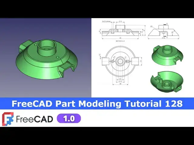
In this video I have explained How to Model Part in FreeCAD with the help of part design Workbench.
▶️ Visit my website for more info on FreeCAD-:
https://mechnexus.com/
▶️ Get my FreeCAD Crash Course for beginner-:
https://www.udemy.com/course/freecad-course-for-beginner/?referralCode=3BA9B526A12F96295D44
▶️ Download Source File of Tutorial-:
https://mechnexus.com/mechnexus-youtube-tutorial-source-file/
▶️ Become my Patron on-:
https://www.patreon.com/c/mechnexus/membership
▶️ Buy Me a Coffee
I am very grateful that you watch my videos and I am constantly trying to improve the quality of the videos on this channel. If you'd like to help me do this, please consider supporting me so that I can to continue to produce content for your enjoyment.
👉 Help support this channel by buying me a coffee: https://ko-fi.com/mechnexus
Show More Show Less View Video Transcript
0:00
Hello friends welcome to Free care
0:02
tutorial number 128 and in this tutorial
0:05
we will model this part as you can see
0:08
that uh I have already modeled it and I
0:12
will show you from the scratch how you
0:14
can model this part as we can see in a
0:18
isometric view one is a top and one is a
0:20
bottom so you can see that it is exactly
0:23
matching with the isometric view
0:27
now we will read the drawing and we will
0:30
model this part from the scratch so I
0:32
will uh close this file and create a new
0:36
file you can also visit my website Mech
0:39
nexus.com where I write articles and
0:43
tutorials on freead you can download my
0:46
tutorial source file from here tutorial
0:49
source file page and you can also
0:52
support me by buying a cup of coffee on
0:57
kofi.com your uh small support will help
1:01
these channels to grow and it will
1:03
motivate me to create more awesome
1:05
content on freead I thanks to all my
1:09
supporter those who have supported me by
1:12
buying a cup of
1:14
coffee so keep supporting and uh it will
1:18
help me to grow this Channel and it will
1:22
motivate me to create more awesome and
1:25
useful tutorials on freeat so let's come
1:29
back to our
1:31
tutorial so here I have created a new
1:33
file and I will insert my body and On
1:36
the Origin
1:37
plane and now we will create our first
1:41
feature which will be the revolve
1:44
feature so we will uh read this drawing
1:47
so first I will Zoom
1:51
it so here we see the DI diameter is a
1:55
56 and angle is a
1:58
50° and
2:00
thickness thickness we can see that it
2:03
is a 1.2
2:07
mm if we go here we can see that here is
2:10
a thickness 1.2 mm so we will select
2:14
this uh front plane and click on the
2:17
sketch select this and
2:20
uh off the origin plane and
2:25
now we will uh create a rectangle
2:31
and uh I will delete this
2:34
line and make this line little bit
2:38
shorter and let's fix the
2:42
height so this height is of 12 mm which
2:46
we can see
2:48
here and I will drag this to down and
2:52
give the dimension for the
2:56
thickness which is 1.2
3:01
and I will move this Dimension and
3:05
now select the line
3:08
tool and uh I will create a rough
3:13
profile and uh I will close it and I
3:18
will select this and this and add the
3:22
parallel and now select the
3:26
dimension and uh give the thickness 1.2
3:31
and uh if you see the side view here so
3:34
this is the diameter
3:37
56 I will uh give the
3:41
diameter 28 which is
3:44
radius and
3:46
now here I will move it and provide the
3:52
angle select this and this and provide
3:55
the angle of
3:58
50° and now
4:02
we will move to
4:06
the the section View and we can see this
4:09
diameter is given here which is the 8 mm
4:13
so we will provide the radius of 4
4:20
mm and I will move
4:24
it so our sketch is fully constrained we
4:28
will come out of the sketch
4:30
and we will revolve
4:32
it and click on okay now let's create
4:37
the next feature so if we go in
4:40
isometric view now we will create this
4:43
pad so I will select the phase and click
4:47
on the sketch and
4:50
here I will create a two
4:54
diameter and we will read the dimensions
4:58
so inner one is a 15 and thickness is
5:01
1.2 so I will select the inner 11 15
5:07
mm select this and this and give the
5:11
thickness
5:12
1.2 click on close now we will uh create
5:16
the pad of 7
5:19
mm because 19 - 12 is a
5:23
7 so we will click on the
5:26
pad and give the value 7 mm say okay now
5:31
let's uh move to the next
5:33
feature so if we see our isometric view
5:37
we see the two pads here
5:41
now we will select this pH and click on
5:45
the
5:47
sketch and now I will
5:50
uh create my
5:55
profile let's read the drawing so here
5:58
it is a 8 mm M plus 1.2 mm thickness
6:03
so the inner diameter is of 8
6:09
mm and this one is of 1.2
6:14
thickness now let's uh switch to the
6:18
wireframe view so that uh you can see it
6:20
clearly now again I will create a circle
6:25
and in this case this is a 15 + 1.2
6:30
so I will give this diameter 15
6:34
mm and
6:39
uh select Dimension select this and this
6:43
and give it
6:45
1.2 now I will close my
6:47
sketch and from here I will switch to
6:50
the flat lines so here best part is
6:54
that freeat 1.0 support the multiple
6:59
sketch
7:00
Extrusion so
7:03
previously this uh two sketch means I
7:07
want to create these two pads that was
7:09
not possible in a fre at
7:11
0.21 but in 1.0 it is possible but there
7:15
is a trick
7:17
so press control key and select
7:22
it and click on the
7:24
pad and this is the pad of 4 mm
7:32
now on the
7:34
sketch and select this
7:37
and this and click on
7:42
extrude and it will be the
7:49
4mm so with a single sketch we have
7:53
created the two Extrusion so that is the
7:56
new feature in a free cat one
8:00
.0
8:02
now let's move to the next
8:07
feature so now if you see our isometric
8:10
view we will create the cut here so we
8:14
require a tangent plane here so our
8:17
diameter is 56 so we can uh directly
8:20
insert a plane at uh distance of a 28 mm
8:25
but here we will learn how we can insert
8:28
the tangent plane
8:30
so click on the plane options select
8:33
this
8:34
point here is a
8:37
Vex and select this
8:40
circumference Free Net TB so you can see
8:45
that a tangent plane has been inserted
8:49
so once I modify this diameter my plane
8:52
will get automatically modified so
8:55
giving a distance plane is not a good
8:57
idea
8:59
because now this plane has been linked
9:01
with my diameter which is a 56 now I
9:04
will uh say rebuilt
9:07
and I will uh select this plane and
9:10
click on the
9:12
sketch and now I will create my profile
9:15
say isometric and switch to the right
9:18
View and we will switch to the
9:21
wireframe and go to the model and hide
9:24
this dat temp
9:25
plane and now here
9:30
I will uh create a
9:33
rectangle and I will delete this line
9:37
and I will select the polyline
9:42
tool and I create a rough
9:47
profile
9:50
now I will make it
9:55
vertical and this also the vertical now
9:58
let's add the symmetricity
10:00
constraint so select the symmetricity
10:03
select this
10:04
point this point and the
10:08
axis and uh this is off a 15
10:15
mm and now I will uh move this
10:20
inside and give the thickness
10:26
1.2 give it a 1.2
10:30
or simply I select this and this and uh
10:34
made it
10:39
equal select this and this and
10:44
uh give it 1.2 and uh let's uh Define
10:51
the height of 8
10:53
mm so our uh sketch is fully constrained
10:57
now I will switch to the the flat lines
11:00
and come out of the
11:03
sketch now I will create a cut of a 15
11:07
mm and this is approximate distance so
11:11
select the
11:16
cut so that it opens inside of my body
11:21
and now we will first mirror this
11:27
pocket select reference
11:30
and select
11:33
it so it is got mirror and now we will
11:38
select the sketch and click on the
11:42
pad click on the
11:46
reverse and let's give it uh 12
11:51
mm click on okay now we will mirror this
11:55
pad click on the
11:58
mirror from here select the
12:05
reference now we will uh on our origin
12:09
plane select this mid
12:13
plane which is at a front location and
12:17
click on the
12:19
sketch and now we will uh switch to the
12:22
wireframe and we will project this age
12:25
so click on the project geometry
12:30
and
12:31
now I will select a line tool and uh
12:34
create a
12:36
line and from here I will select the
12:40
horizontal line select
12:43
Dimension and uh give the dimension 15
12:47
mm and click on the project
12:50
geometry so that it is projected and now
12:54
I will uh select a line tool
13:00
and I will close my
13:06
profile and here coincidence relation so
13:10
that is happened because of origin plane
13:13
so I will off the origin
13:15
plane and click on the
13:24
coincidence and now I will close my
13:26
profile
13:30
so our profile is fully
13:32
constrained we will come out of the
13:37
sketch and
13:39
now I will switch to the flat
13:44
lines and uh I will use the Revol
13:49
cut and from here I will select the
13:51
reference which will be the Z axis
13:59
so here wire is not closed so we will
14:02
identify the issue select the sketch and
14:05
click on the validate
14:07
sketch and uh we will switch to the
14:11
wireframe view so here is the
14:16
issue so I will close it and I will
14:19
delete this
14:22
line now close it select the sketch
14:27
click on Revol
14:30
so you can see that material has been
14:32
removed click on
14:35
okay now let uh switch to the flat lines
14:39
so it done so
14:41
perfectly now we will uh move to the
14:44
next
14:45
feature which is if you see in a inside
14:49
view so here is a rib so we will add
14:52
this
14:54
rip so we will uh select this pH
15:04
and let's
15:05
see this and this on the same
15:09
level so here we will measure the
15:12
distance so Delta Z is zero if you see
15:16
our UCS with the isometric view so Delta
15:20
Z is zero which means that they send
15:22
this at the same level so either we can
15:25
select this phase or this phase for the
15:27
sketching but but I will prefer this
15:31
face and uh click on the
15:35
sketch and uh I will project this outer
15:38
diameter click on the
15:41
project and now I will also project this
15:45
Arc and
15:49
here I will select a three-point
15:56
Arc and I will select this and this this
15:59
and uh make it
16:02
equal select the three-point
16:07
Arc and I will uh connect
16:12
it this
16:15
and with this and I will make it
16:18
horizontal and now here I will make this
16:21
symmetric with this axis I will select
16:24
symmetricity constraint select this
16:26
point this point and this axis
16:30
so one degree of
16:33
Freedom so that will be get solve with
16:37
Dimensions so I will Define the
16:39
thickness of 1.2
16:51
mm click on
16:54
close now select the sketch click on the
16:57
pad
17:01
and select up to
17:07
face and click on okay now we will uh
17:11
mirror this on the other side so select
17:14
this pad click on the
17:18
mirror and from here select reference
17:21
and select this mid
17:23
plane click on
17:25
okay but due to this there is a material
17:28
came here
17:30
outside so we will remove it with a
17:34
Revol cut so let uh set our model to the
17:38
isometric View and uh now on the origin
17:42
plane now select this exit plane and
17:45
click on the
17:48
sketch and from here we will uh switch
17:50
to the
17:52
wireframe and click on the project
17:57
geometry and and
18:01
now we will close this
18:14
profile now we will close it select the
18:18
sketch click on the Revol
18:22
cut select reference and uh select this
18:26
Zed axis
18:29
so here some material
18:32
is remain here so we will uh little bit
18:37
modify our
18:40
sketch so here what I will do I will
18:45
uh rotate my model
18:49
and I will
18:54
uh delete it
19:01
let's press contrl
19:04
Z and delete this line and
19:09
here I will also delete this line and
19:13
from front view I will create a
19:18
line which will be come outside of this
19:21
little bit so let's give some rough
19:22
dimension
19:29
let's edit the
19:35
sketch now I will give it a
19:42
3.2 now switch to the front view and now
19:46
I will select a line
19:49
tool create a line
19:52
and coincide this line with this point
20:01
and
20:03
now let's make it uh
20:08
2.8 or
20:12
2.5 select the line
20:17
tool and made it
20:20
vertical and let's make it 2
20:24
mm uh not 2 mm little bit 2.2
20:29
yes now it will not left any material so
20:32
close it and let's switch to the flat
20:41
lines now select the sketch click on the
20:44
Revol
20:48
Cod say
20:51
okay so we have created the
20:54
rip now let's uh move to the next
20:57
feature
21:00
so our next feature is to create these
21:03
two
21:04
pads and for this we will create a DM
21:08
plane at a distance of 8 mm from the
21:13
bottom because if you see in our
21:16
drawing so this Dimensions come the 8
21:22
mm so select the face and uh create a
21:30
offset distance plane 8 mm so I will
21:33
select this pH and click on the data
21:35
plane and in a z Direction I will uh
21:39
give it minus
21:41
8 you can read this Dimension here in a
21:50
drawing so now let's switch to the front
21:53
view
22:01
click on okay so here we will Rectify
22:05
our
22:09
Revolution to check the
22:11
height so height is
22:16
okay so if you see that
22:20
here we wanted to create this tab so
22:25
from the top it is 8 mm
22:30
not from the bottom so it is okay so
22:33
what we will do we will edit our dat
22:36
temp
22:36
plane and here reference so we will
22:40
delete this reference and we will select
22:43
this plane so now it is perfect of the 8
22:47
mm and now click on
22:49
okay now we will
22:52
uh select this plane and uh create a
22:55
sketch
22:58
and now I will rotate it switch to the
23:00
bottom View and here if you see the PCD
23:05
diameter is of
23:08
28 so I will uh select a
23:11
circle and it will be 14 so select the
23:15
smart Dimension and give it a
23:19
14 and give it a diameter of of
23:24
5mm click on close
23:31
now we will off the DAT temp plan select
23:33
the sketch click on
23:38
extrude and here we will select up to
23:41
phas and we will select this
23:43
phas click on
23:46
okay now we will mirror this features on
23:49
the other side as we can see in
23:51
isometric View and then we will create
23:54
these two holes so select the pad click
23:58
on the
23:59
mirror and from here click on select
24:03
reference and select This Plane click on
24:08
okay
24:10
now we will uh select this pH and uh
24:14
create a
24:16
hole which is of
24:20
2.6 so click on the sketch and uh click
24:25
on the project
24:26
geometry select this and this and uh
24:31
create two
24:36
circles select
24:38
diameter and provide it
24:42
2.6 this is of for
24:45
2.6 and if you see the isometric view so
24:49
this hole is a through which is visible
24:51
on this top face click on close select
24:55
the sketch click on extrude cut
24:59
and uh simply say it through
25:02
all so it is opening on the other
25:06
side now all we do is to add the
25:12
fillet so first I will add the fillet
25:16
here I will press the control key and uh
25:19
select this all four edges and click on
25:22
the
25:25
fillet this fillet I will give the 3 mm
25:29
click on
25:32
okay
25:34
now we will create the inside
25:38
flet so I will click on the
25:42
fet and select this
25:46
sge this
25:51
ede this
25:55
Ed and this Edge and Prov write the
25:59
radius of 1.8
26:05
mm click on
26:08
okay
26:10
now place our model to the isometric
26:13
view now we will select this age and uh
26:16
provide the fillet of 1
26:20
mm click on
26:24
okay and
26:26
now we will provide some fillet here so
26:31
select this
26:32
H and this H so best thing about the
26:37
fread 1.0 is that even I have not
26:40
selected the all the ages but it will
26:43
automatically take the tangent
26:45
propagations so once I click on okay it
26:48
will automatically create a
26:51
fillet so you can see that it
26:53
automatically took the tangent
26:56
propagation
26:59
so you can see that we have successfully
27:02
converted this drawing into the 3D
27:05
model and here is a problem of the
27:09
fillet let's uh give this fillet in a
27:11
one
27:15
shot select this H this
27:21
H this
27:23
H and this
27:26
H and let let's click on
27:30
okay yes so now it
27:34
perfectly given the fillet and now we
27:38
will
27:39
do the color as per our uh isometric
27:44
view so all I will do is go to the
27:47
appearances and I will scroll down and
27:50
go here at a custom appearances and
27:53
select the
27:55
color click on close
28:04
now this completes our model and uh we
28:08
have successfully modeled this uh part
28:13
with the respect to this orthographic
28:15
drawing and we have a
28:17
match our model with the isometric view
28:20
so this is all about the this tutorial
28:24
thank you for watching and thank you for
28:26
your valuable time
28:31
[Music]
#CAD & CAM