live_tv
Livestream Starting Soon
00
Hours
:
00
Minutes
:
00
Seconds
Up next in 10

#freecad #freecadtutorial #freecadpartdesign
In this video I have explained How to Model Part in FreeCAD with the help of part design Workbench.
▶️ Visit my website for more info on FreeCAD-:
https://mechnexus.com/
▶️ Get my FreeCAD Crash Course for beginner-:
https://www.udemy.com/course/freecad-course-for-beginner/?referralCode=3BA9B526A12F96295D44
▶️ Download Source File of Tutorial-:
https://mechnexus.com/mechnexus-youtube-tutorial-source-file/
▶️ Become my Patron on-:
https://www.patreon.com/c/mechnexus/membership
▶️ Buy Me a Coffee
I am very grateful that you watch my videos and I am constantly trying to improve the quality of the videos on this channel. If you'd like to help me do this, please consider supporting me so that I can to continue to produce content for your enjoyment.
👉 Help support this channel by buying me a coffee: https://ko-fi.com/mechnexus
Show More Show Less View Video Transcript
0:01
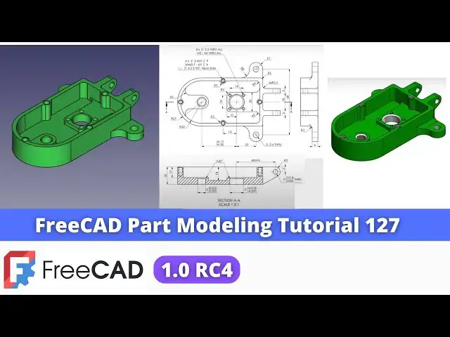
Hello friends Welcome To freeat tutorial and in this tutorial we will model this part and this is the tutorial number 127
0:09
so as you can see that uh I have already converted this uh 2D drawing into the 3D
0:15
model and you can see that my model is matching with the isometric View and I
0:22
have given the exact color as per our isometric view so we will read
0:30
this drawing and we will create this model from the scratch and uh for
0:35
modeling I have used the freead version 1.0 and this is the rc4 release so if
0:46
you have not installed the latest version of a freeat then install it and
0:51
if you are a Windows user then I have already made a video on my YouTube channel how you can run
0:58
freead 1. 0 rc4 on your Windows system so follow the
1:06
instruction in a video and install the free care version on your Windows system
1:15
if you are a using the Mac or Linux then you can find the relevant videos on
1:20
YouTube so I will uh close this file and I will create a new file you can also
1:27
visit my website macn nexus.com where I write articles and tutorials on freead
1:34
you can download my tutorial source file from here tutorial source file page and
1:40
you can also support me by buying a cup of coffee on kofi.com your small support
1:49
will help these channels to grow and it will motivate me to create more awesome content on fread I thanks to all my
1:58
supporter those who have supported me by buying a cup of
2:03
coffee so keep supporting and uh it will help me to grow this Channel and it will
2:11
motivate me to create more awesome and useful tutorials on freeat so let's come
2:18
back to our tutorial so here I have created a new
2:23
file and first thing which I will do is to insert a body and I will press the
2:29
space bar and and on my origin plane now we will read our drawing so so first
2:37
feature which we will make is this base one so for this we will select this top
2:42
plane and click on the sketch and go to the model Tab and hide
2:49
the origins and now I will simply create a
2:56
rectangle and I will delete this line and I will I will select uh threep Point
3:02
Arc select this and this and create an arc and now I will add the tangency
3:10
relations here and here and we will make this symmetric so
3:16
we will click on the symmetricity constraint select this point this point and this
3:21
axis now select the horizontal Dimension and uh provide the dimension
3:28
50 and this Dimension we can see here r25 therefore
3:35
it is a 50 and from the h to the
3:42
center total Dimension is uh 63 you can check the dimension as I have
3:50
already modeled it so I know it but you can add the dimension and you can get
3:56
the values now I will come out of the
4:03
sketch and uh extrude it to the distance of 18 mm select the sketch click on
4:10
extrude and uh provide the distance 18 mm say
4:18
isometric now this is the dimension 18 which we can see here and now we will move to the
4:26
next feature which is to remove the material and create this hollow so for
4:33
this we will create this profile and we will create a cut so we will select the
4:41
stop pH and click on the sketch and we will again create a
4:48
rectangle and delete this
4:55
line and select a three-point Arc select this one and this
5:04
one from here let's uh switch to the wireframe so here this point is not
5:12
merge so we will select this two and add a coincidence now I will add the tangency
5:19
relation select this and this and add a tangent select this and this and add a tangent now here we will also make this
5:26
symmetric so we will click on symmetricity select this point this point and this
5:33
axis and from this AG to this Dimension is of 3
5:42
mm and this is the radius of uh
5:50
22 and this will be the concentric so we will click on the
5:57
project geometry and project this radius so we get a Center Point all I have to
6:02
do is click this both Center points by pressing the control key and add a
6:08
coincidence so now our uh sketch is fully constrained and now I will remove
6:15
the material to the depth of a 14 mm the 14 mm Dimension we can see here
6:23
select the sketch click on the pocket and provide the 14 mm click on
6:29
okay now let's move to the next feature so next feature is to create this boss here
6:37
and if we go in a drawing so we can see here the boss in isometric view so we
6:42
will select the face and uh click on the sketch and first thing is to project
6:49
this inner Arc and switch to the model to the wireframe and
6:56
now select the three-point Arc create an arc
7:01
and now select this and this and add a coincidence and here I will select the
7:08
diameter constraint and provide a diameter of 14
7:15
mm and now I will stretch this
7:21
Arc and here I will create a three-point AR equal to this projected one so select
7:29
the AR select a three-point Arc and select this and this and add equal
7:36
constraint and select this point of Arc and this one and add a
7:44
coincidence so let's uh yes this is the point so we will select this and this
7:50
and add the coincidence now I will shorter this Arc
8:01
so move to the front view now we will connect this two with a
8:09
line so select the line tool select this select this and this and add it as a
8:19
vertical constraint select this and this and add a tangent select this and this and add a
8:27
tangent and click on close switch to the Shaded
8:37
view again select the Shaded and then flat lines and now we will add the
8:42
material to the thickness of a 3
8:48
mm so we can see here the thickness is 3 mm because if you minus 14 - 11 we will
8:55
get a 3 mm so select the sketch
9:00
and provide the value 3mm click on okay
9:05
now we will create this boss here and if you go
9:11
in isometric view we can see here so we will again select the phase and click on
9:17
the sketch and here I will click on this inner Ed and switch to the
9:25
wireframe and create a rect triangle and now I will make this
9:33
symmetric so click on the symmetricity select this select this
9:39
point and this point select this and this and this
9:45
axis and now select smart Dimension and
9:54
uh provide the length select it and uh give the value
10:00
20 mm and this is of
10:05
37 click on close switch to
10:12
the flat lines and now we will add a
10:18
material of 3 mm here as well so select the sketch click on the
10:24
pad and give the 3 mm click on okay
10:30
now let's uh move to the next feature so now we are doing the material addition
10:36
operations this cut and material removal operation we will do later so now we
10:42
will create this two
10:48
leg or we can say the mounting phas so select the phase and
10:56
uh switch to the isometric so now I will project this age click on
11:03
the project geometry and we will project it and now here I will
11:09
uh create a rectangle select this point and uh delete this line and here I will
11:18
select a three-point Arc and add a
11:25
tangent add this and add a tangent and now I will provide the radius of 7
11:38
mm so here we can see that R7
11:44
and from this Center to this origin is of
11:52
34 click on close and click on the pad select the
11:58
reverse and the thickness is of 6
12:05
mm which we can see here give the value 6
12:11
mm click on okay now let's move to the next
12:16
feature so next feature is to mirror this on the other
12:21
side because this and this is a same so select the pad click on the
12:27
mirror and from here select the reference and I will select this mid
12:34
plane so you can see that it got mirrored perfectly now let's uh move to the next
12:41
feature and next feature is to add a material at these four locations so
12:49
first thing which we will do is we will create this one and we will mirror it on the other sides so for this I will
12:57
select this top face and uh click on the sketch and here I will project this
13:06
age and here I will uh select a circle and I will give the
13:17
radius select radius and give the radius of a 3 mm and
13:24
now I will use the trim tool to trim this
13:32
and now let's uh close the
13:38
loop click on close now select the sketch click on the
13:44
pad click on reverse and this will be up to phase so
13:51
select uh up to phase and select this face and click on
13:57
okay now we will mirror it on the other side so select the pad and uh click on
14:05
the mirror options and from here select the
14:10
reference and I will select this mid plane and click on
14:16
okay and now I will create same profile
14:22
here so select this top face and uh click on the
14:28
sketch click on the project geometry and project this inner Arc and now select the three-point
14:37
Arc and create one approximate Arc and now select this and this and add a
14:45
coincidence select this and this and add a
14:50
vertical and uh select the radius options and provide the radius of 3 mm
14:59
and to close the profile we will create equal radius for this projected Arc so
15:05
select a three-point Arc and select this and this
15:10
and I will select both and made it equal so our profile is fully constrained we
15:18
will come out of it select the sketch click on the pad and Define the end
15:23
condition up to face select this click on okay
15:29
now we will create one more boss here so we will do the same procedure select the
15:35
phase click on the sketch click on Project geometry project
15:41
this inner one select the circle and click on the trim option trim
15:51
it and select the line tool select this and this and uh
16:01
provide the value R3 and select the sketch click on the
16:07
pad from here select up to phase and select the phas click on
16:14
okay now let's uh move to the next
16:19
feature which is to create these
16:25
two pads so for this we require a datm plane at a distance of 9 mm because here
16:33
is a dimension 18 so I will create an offset plane at a 9 mm distance so I
16:40
will on my origin plane select this mid plane and click on
16:46
the datm plane and here in a z Direction I will provide Min - 9
16:54
mm so you can see that uh plane is created now I will off the origin plane
17:01
and here is a Blue Tick so I will simply refresh my model now select the data plane and click on the sketch and let's
17:09
create the profile so we will project the age so we will
17:18
click on the project
17:23
geometry and switch to the right View and from here we will switch to the
17:30
wireframe select the line tool create a line and
17:37
then create a triangle
17:42
profile and now we will provide the radius of R5 so go to the radius options so here
17:51
is a fillet click on create fet give the fillet
17:57
and now provide a dimension to the fillet select uh
18:04
radius and this is the 5mm
18:11
and this line will be the horizontal to make it horizontal now select the smart
18:16
Dimension select this and this and provide the value 13 mm click on okay
18:24
now off the DM plane and from here switch to the flat lines
18:34
okay now our profile is ready and now we will create a pad of a
18:41
5mm so select the sketch click on the
18:47
pad so here I will reverse the direction because I want on the other
18:53
side and provide the thickness of a 5 mm
19:02
click on okay and now uh we will mirror this on the other side to select the pad
19:07
and click on the mirror and uh select the
19:13
reference and uh click on this mid plane and click on
19:21
okay and uh let's move to the next
19:26
feature after mirror of this pad let's switch to the
19:32
isometric and now we will provide the
19:37
fillet because we have a overall shapes we have completed now it is time to
19:44
provide the fillet so here if you see here is a fillet of RFI at four location
19:51
1 2 3 and four so we will click on the
19:56
fillet and uh we will select this corner HED this
20:03
one this one and two on the this
20:10
side let's move it and select
20:16
this and this and here I will give the value
20:22
five and click on okay now
20:29
we will uh provide the fillet of R3 at two
20:35
locations here R3 on these two locations so we will again click on the
20:41
fillet and set the value three and select this hge and this
20:51
hge this and this value set three click on okay
20:59
now let's uh move to the next feature next feature is to provide the fillet of
21:05
uh R8 at this locations and this locations so we will again click on the
21:13
fillet select this H
21:18
and this H and set the value 8 mm click on okay so you can see that
21:27
fillet has been added now move to the next feature which is to provide the fillet
21:34
of R3 at all four features which we have created so click on the
21:42
fet and select this H this
21:50
H this one this one
22:02
this this this
22:13
age and set the value of
22:19
three and click on okay so you can see that fillet has been
22:27
added now press zero for isometric View and
22:33
now let's uh add a fillet of uh
22:42
2.5 so if you see here so four radius of a 2.5 means two this and two this so we
22:50
will again select a fillet and select this
22:56
H this h this
23:01
Ag and this one and set the value of 2.5
23:08
and click on okay now let's uh move to the next
23:18
feature which is to provide a fillet of
23:26
R4 at this locations and this location so click on the
23:34
fet select this age and this
23:42
age and click on values provide the 4 mm click on
23:52
okay now let's move to the next feature now we have added the material
23:59
and we have provided the relevant fillet at all locations now it is time to
24:07
remove the material so this is the basic modeling practice first you have a
24:13
create a feature of additions then
24:18
subtractions because in your model tree your holes should become at the end it
24:24
is not like that you created a pad and then created a hole here then again created the pad at a whole year so the
24:31
benefit of is this is that you will get all material addition feature at the
24:36
same locations and all material removal feature as a same locations like hole
24:42
cut Etc so let's create this four holes
24:47
of diameter 4 so
24:52
here if you see our drawing
24:59
so here is a section A is given and here are the those
25:05
holes so call out of this hole is 4 into 3.4 63 drill and M4 of a at
25:18
a distance of a 6 mm so let's uh create
25:24
it so first we will select the phas and uh click on the sketch and now I will click on the
25:32
project geometry I will project all for
25:46
radius and create a diameter four holes at four
25:53
locations let's uh create one here
25:58
one here one
26:04
here one here now select the diameter
26:14
options do the 4 mm and select this
26:22
radius and by pressing the control key select all four
26:29
and provide here equal constraint now click on okay now select the sketch and
26:35
click on the whole Wizard and from
26:42
here we will select the isometric regular
26:49
profile and it is M4 M4 and
27:00
Dimension we will provide the 6
27:08
mm click on okay and now we will provide the chamfer
27:16
of Point 2 this is approximate Cher so now click
27:24
on the chamfer and select this
27:31
this this and this and give your
27:38
value2 click on okay now let's uh move to the next
27:46
feature now we will create this hole so we will uh select the face and click on
27:53
the sketch so it is a simple drill hold
27:59
so we will make with a cut select the
28:08
circle and this is of 8 mm and provide the dimension 8 mm click
28:17
on close select the sketch click on extrude
28:25
Cut and from here say it through all say okay now here is a chamfer of 1
28:35
mm but we will provide the 05 because uh 1 mm looks too large so select it and uh
28:42
provide the chamfer of5 click on
28:50
okay now let's uh move to the next feature which is to create a hole at
28:56
this locations so so we will select the ph and click on
29:01
the sketch and we will select the circle tool and uh create a circle and now we
29:10
will project this uh radius click on project so that we get a center
29:16
point and we can see that from here to here it is a 20 mm so we will select the
29:22
smart Dimension and provide the 20 mm
29:28
and this is the hole of 14
29:34
mm click on okay select the sketch click on extrude
29:45
Cut and from here say it for click on okay
29:52
now we will provide the chamfer of A5 mm here
29:59
select it select the chamfer and provide the5
30:05
mm click on okay now we will create this four holes at
30:15
four locations so we will select the face and uh click on the
30:21
sketch here I will uh project this diameter click on Project geometry
30:28
and project the diameter and select a
30:37
rectangle and now I will uh select all and make it
30:47
construction and from here I will use the symmetricity select this this and this
30:53
origin point to make it symmetric and now
30:58
I will create four holes at this Four Corners
31:04
so select Circle and create a for
31:16
Circle and select diameter and provide the
31:24
3mm and now select all by pressing the control key and made it
31:31
equal and uh this and this made it
31:37
equal and uh select smart Dimension and provide it a
31:45
14 click on okay so this is
31:50
a 4 into 2.5 and M3 through all
31:57
so we will make M3 through all so click on the whole
32:16
wizard I will delete it select the
32:21
sketch click on the whole visit
32:28
and here we select a isometric regular profile and from here it is size of M3
32:36
and let's make it through
32:43
all so there is a no any point of this 2.5 mm drill we will make this M3
32:50
through allall so this is a mistake in drawing there is a no any point to mentions diameter 2.5 now let's
32:59
uh move to the next feature which is to create uh these two
33:09
holes so for this we will uh simply
33:14
uh create a hole with the help of a cut now instead of using mirror I will
33:22
project this both Arc and create a hole so do not use the mirror tool unten
33:29
and unless it is necessary if here I can do both the holes in the single
33:37
sketch but for drill hole also use the whole feature but I am using the cut
33:45
feature and uh select this and provide uh 6
33:52
mm so we can see that uh two dasis through so I will uh select this and
34:01
this and uh made it equal now click on close select the sketch click on
34:09
Cut and say it through
34:18
all and now we will uh create a hole of a 5mm on these two pads
34:27
here which we can see in isometric so here I will simply create a hole here and make it through all so select the
34:36
face and click on the sketch and this is off a diameter five so project the
34:43
geometry select the circle and create a circle and select a
34:51
diameter and provide the 5mm click on close select the sketch
34:58
click on extrude
35:04
Cut and from here say it through all or we can also Define end condition
35:12
to this phas that is your choice no
35:17
issue now we can see that we have completed our models and now we will
35:23
apply the color to our model as per isometric View so I will select this
35:29
last features go to the appearances and here I will go in custom
35:35
appearances and here is a diffuse color and here I will select
35:40
the green color and click on Okay click on
35:46
close so this is how we have completed this model from the scratch in freeat
35:53
part design workbench so this is all about this tutorial thank you for watching and thank you for
36:00
your valuable time
#CAD & CAM
#Sculpture