live_tv
Livestream Starting Soon
00
Hours
:
00
Minutes
:
00
Seconds
Up next in 10

#freecad #freecadtutorial #freecadpartdesign
In this video I have explained How to Model Part in FreeCAD with the help of part design Workbench.
▶️ Visit my website for more info on FreeCAD-:
https://mechnexus.com/
▶️ Get my FreeCAD Crash Course for beginner-:
https://www.udemy.com/course/freecad-course-for-beginner/?referralCode=3BA9B526A12F96295D44
▶️ Download Source File of Tutorial-:
https://mechnexus.com/mechnexus-youtube-tutorial-source-file/
▶️ Become my Patron on-:
https://www.patreon.com/c/mechnexus/membership
▶️ Buy Me a Coffee
I am very grateful that you watch my videos and I am constantly trying to improve the quality of the videos on this channel. If you'd like to help me do this, please consider supporting me so that I can to continue to produce content for your enjoyment.
👉 Help support this channel by buying me a coffee: https://ko-fi.com/mechnexus
Show More Show Less View Video Transcript
0:00
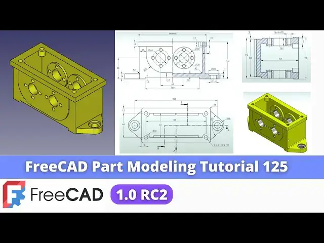
Hello friends welcome to Free tutorial and in this tutorial we will model this part from the scratch as you can see
0:07
that I have already modeled this and my freead model is a matching with a
0:12
isometric image and uh this is the isometric
0:18
drawing which is having the orthographic view of a front top and
0:24
side and here I have referred this autographic drawing and converted into
0:29
the 3D mod model and I will show you from the scratch how you can model this part with the help of a part design
0:36
workbench so I will close this file and create a new file you can also visit my website
0:44
machne nexus.com where I write articles and tutorials on freead you can download
0:51
my tutorial source file from here tutorial source file page and you can
0:56
also support me by buying a cup of coffee on kofi.com your small support
1:04
will help these channels to grow and it will motivate me to create more awesome content on fread I thanks to all my
1:13
supporter those who have supported me by buying a cup of
1:18
coffee so keep supporting and uh it will help me to grow this Channel and it will
1:27
motivate me to create more awesome and useful tutorials on freeat so let's come
1:33
back to our tutorial so here I have created a new file and I am using the
1:40
freead version 1.0 it is a rc2 release and if you have not installed it
1:47
then install it on your system if you are a Windows user then you can refer my
1:52
YouTube video on uh my YouTube channel where I have shown how you can run
1:57
freeat version 1.0 on on windows so here I have activated the part design
2:03
workbench and first thing which I will do is to insert the body and I will start the
2:12
sketching so first which I will do I will reduce the
2:19
my image and here first thing which I will do is to refer the autographic
2:27
drawing so first we will do we will model this top feature so for this I
2:33
will select this exit plane and click on the sketch and uh off this origin
2:42
plane so now we will Zoom it and first we will
2:48
create this uh rectangle profile at a height of 102 and thickness of a 12
2:56
mm and it would be symmetric to this axis so select the rectangle create a
3:04
rectangle and now I will use the symmetricity
3:10
constraint so I will select the symmetricity select this point and this
3:16
point and this axis and it is a symmetric and now from this point to this point I will
3:25
uh provide the dimension of 102 and uh thickness of uh 12
3:34
mm 202 this is the 190 Dimension which is
3:41
incorrect when I model this part so instead of 190 give it
3:46
202 close it and now we will extrude to the
3:51
distance of 96 and
3:57
uh we will keep it metric to the plane and click on okay now I will On the
4:05
Origin plane and select this exit plane and click on the
4:12
sketch and uh off this
4:18
origin now we will click on the project geometry switch to the
4:24
wireframe select a rectangle and
4:30
and now we will uh give the
4:36
dimensions to this sketch so first thing is to make it
4:42
symmetric so click on the symmetricity constraint select this this and this
4:50
axis and now also I will project this
4:56
topage and because this is the
5:05
102 from the bottom so what I will
5:12
do I will select smart Dimension select this point and this
5:21
point and now let's give the horizontal dimension of a 192
5:32
so some of the dimension are the incorrect that's why I am uh because I have already model this part so you have
5:39
to follow the few Dimensions as per my sketching and rest
5:45
is follow from this autographic drawing so now you can see that uh our sketch is
5:52
fully constrained now I will close it and provide the Extrusion of 86 mm 86
6:00
and click on the symmetric to the plane click on
6:05
okay and uh now we will uh select this bottom face and we will create this
6:12
profile so select this bottom face and click on the
6:18
sketch and we will click on the project geometry project uh this H and
6:25
now I will select the line create
6:31
line and
6:37
uh provide the radius of uh 18 mm so I will choose the fillet option to
6:46
do that select this and this and provide
6:54
the fillet
7:02
and uh 18 mm and select this and this provide the
7:11
horizontal relation here we will make this two points symmetric so click on the
7:18
symmetricity select this point and this point and this axis and here is a
7:24
conflict constraint which is the horizontal one we will delete it and from from Center this Center to this
7:32
Axis Center is of 114 select this and this and uh provide
7:39
the 114 and uh now we will constrain the
7:45
angle so select smart Dimension select this and this and uh provide the 40
7:54
mm click on okay and now click on the
8:00
pad Tab and click on the reverse and here provide the thickness is of 14
8:07
mm click on okay and now we will mirror this features on
8:15
other side of our part so select the features go to the mirror option and uh from here select reference
8:24
select mid plane click on okay
8:29
Set uh isometric position and now the next feature is
8:37
to create this pad so this is the same on the other
8:45
side so we will select the phase and click on the sketch and now we will
8:53
uh draw the horizontal line and for better visibility we will
8:59
uh switch to the wire frame and we will uh click on Project
9:07
geometry and here I will draw the two vertical
9:14
line make it a vertical and now I will select a
9:22
three-point Arc select this and this select this and this
9:30
and select this and this and add a tangent this and this and add a
9:41
tangent this and this and add a tangent and here we will uh close the
9:57
profile so here point is not merge so we will uh select this line and point and
10:05
let's add a con and constraint now we will project this hede and this
10:12
hede because we wanted to fix the position so I will select this Edge and
10:20
this Edge switch to the front view select the dimensions select this and this and it
10:28
just off 18
10:38
mm 18 mm and uh from this to this is of 18
10:49
mm and from the bottom to this one is off for
10:56
12 and uh from the bottom to this uh Center Point is of
11:07
58 now let's uh move to this uh front view we can see here
11:13
1512 and this radius is
11:20
50 and it is already constrained so just cross check the
11:25
radius how much it is so this is
11:31
46 not 50 so correct this as well now
11:36
select this and this and add equal
11:44
constraint now we will close it switch to
11:50
the flat
11:56
lines select the sketch click on the pad and provide here
12:04
3mm and uh click on the pad click on the mirror and from here select reference
12:11
and select the plane exit to mirror it on the other side click on
12:19
okay press zero now move to the next
12:25
feature which is to create a cut now we will create a cut here at the bottom
12:33
side so I will select the face and uh click on the
12:39
sketch select the rectangle
12:45
tool create a rectangle and uh we will uh make it uh
12:51
symmetric select this point to this point and uh provide the dimension of of
12:59
uh 150 and thickness of 5
13:08
mm click on close select the sketch click on the
13:14
cut and from here say through all say okay now we will move to the next
13:22
feature which is to create a cut at a top if we go to our isometric here here
13:29
we can see that uh here is a rectangle so we will select the face and
13:35
click on the sketch and from here we will switch to the flat
13:41
lines select a rectangle tool create a rectangle and from here let's switch to
13:49
the wireframe now we will make this point and this point symmetric to the origin so click on the symmetricity
13:57
select this point this point and this point and uh provide
14:03
the dimensions Dimension we can see
14:09
here so this is the 66 and uh here it is off 12 mm 12 mm 190
14:20
so first select the SM Dimension and provide the
14:27
66 and uh this is
14:33
the
14:38
166 click on close switch to the flight
14:49
lines so this is the cut profile select the sketch and uh go to the cut and
14:57
provide the depth of 87
15:09
mm now let's uh move to the next feature which is to add a material at these four
15:17
locations and to understand in isometric view we are now going to make these
15:24
features so select the face and uh click on the sketch
15:29
switch to the isometric and from here switch to the flat lines and we will project this
15:37
edges click on the project geometry project this
15:42
this this and
15:48
uh we will uh select a line
15:55
tool and switch to the wireframe and here select a three-point
16:06
Arc and this is of a radius r10 we can see this Dimension
16:14
here so first give the radius
16:22
10 select this and this and add the
16:28
coincidence Rel ation we will draw the similar profile
16:34
on the other site select a circle or select a
16:43
three-pointer if you select the circle you can trim it now I will uh create
16:49
here the Treepoint Arc select this and this and uh add a coincidence constraint
16:56
select this and this and add constraint click on close and from here
17:04
switch to the flat
17:09
lines so there is a bug in freeat because once I switch to the
17:16
Shaded view then I can only go to the flat Lines no
17:22
issue now uh we will uh add a material here and uh
17:29
click on reverse and provide this 14 mm click on
17:37
Okay click on the pad and click on the
17:42
mirror and from here select reference and select a mid
17:49
plane and uh now if you see in a top view we can see
17:58
that uh circular pad is there there are the four circular pad and if we go to
18:04
the isometric view we can also see that so we will select this inside face and
18:11
click on the sketch and switch to the
18:17
isometric and from here we will switch to the flat lines and here we will
18:23
create two circles one here and one here select this and this and
18:32
uh provide the
18:38
dimensions switch to the isometric rotate model and provide this 60
18:46
mm and uh we will make this symmetric to this
18:52
Axis or we will project this Arc
18:59
click on the project project this one and uh project this one so that we get a
19:08
point now all I will do is to click this and this and set merge similarly this
19:15
and this and set merge so our sketch is fully constrained
19:23
select the sketch and uh click on the pad and here pad will add of of the
19:34
5mm now we will say okay now we will mirror
19:42
this pad on this face so select the pad
19:47
and click on the mirror options and from here I will select
19:54
reference and select this mid plane so you can see that it has been
20:00
mirror on the other side now press zero for isometric View and now we will uh
20:07
create this through hole which we can see here in isometric View and once we
20:14
create these two holes we will create this small holes so it is very simple all you have
20:21
to do is Select this face and uh click on the
20:26
sketch click on the project geometry and uh select the
20:36
circle and uh provide the diameter of uh
20:48
28 select this and this click on the
20:55
cut and uh remove the material from here say it
21:01
through all say okay now we will create this
21:12
hole which is visible in a front view so select the face and uh click on
21:20
the sketch and here I will click on the project
21:25
geometry switch to the wireframe
21:32
select the circle and we will uh make it a
21:38
construction one and this is of a diameter 44 so
21:45
select it diameter and uh give it a
21:53
44 now we will create a circle
22:01
and select this and this and add a vertical relation so that is the beauty
22:06
of freak at 1.0 when you apply this constraint it
22:11
automatically detect whether it is a horizontal or vertical one select the
22:18
diameter constraint and give it a for diameter
22:23
10 click on close and uh from here we will switch to
22:30
the flat lines so this is the bug first I have to
22:37
switch to the Shaded and then go to the flat so
22:42
now we will uh create the hole and this is the M10
22:50
hole if you see in a drawing here so 4 M10 hole here and 4 M10 hole is here
22:59
which you can see here in a section
23:04
view you can see that so
23:09
here this is of the 18 mm thickness wall thickness is so if I select this phase
23:16
and this phase so this is the 18
23:23
mm and here is the 18 so here is a M1 at
23:29
a 16 mm so tapping is up to the depth of 16 mm so we will select the
23:36
pH uh select the sketch and click on this uh whole Wizard and here we will go
23:44
with the isometric regular profile and from here we will uh select
23:50
the size of M10 and depth depth we cannot say it
23:55
through all we will uh give the distance of
24:03
uh 16 mm and
24:13
here here is a type of the hole so which we are not going to use it so in this
24:22
case we will go with the threaded option
24:29
so here we will give here the depth 18
24:37
mm and threaded is of 16 mm so we can see here so 18 mm is our depth and which
24:46
is opening here and 16 mm is of threaded threaded length is given
24:54
16 we will close it and now we will select the hole and uh
25:02
click on the circular pattern and from here we need four
25:09
holes 1 2 3 and four we will give four and uh here we
25:17
will select reference and we will select this diameter for the pattern and click
25:23
on the okay now we will select this pattern and let's
25:28
mirror on the other
25:36
sides so here additive and subtractive feature cannot be transformed
25:43
so what we have to do is Select this hole and click on the
25:54
mirror and from here select reference select this mid
26:00
plane click on okay now let's uh try to mirror
26:09
this with a polar pattern so here is the same problem
26:32
now we will create a hole if we go to the side view we can
26:38
see that uh hole is of depth of 18 mm but uh
26:43
tapping is of 16 mm so we will select the sketch click on the whole
26:49
Wizard and here we will uh give the depth of uh 18
26:55
mm but first we will select here the isometric regular profile and uh select
27:02
the M10 18 mm is of my depth and go to the
27:09
threaded and uh whole
27:15
depth
27:23
here select the dimensions and uh provide the 16
27:29
mm which means that uh our hole is of 18 but tapping is off
27:35
16 click on okay now select the hole click on the
27:42
Polar pattern and from here we will uh set
27:50
quantity 4 because we need four holes and uh from here we will select
27:57
reference and select this diameter click on okay so pattern feature cannot be
28:04
mirrored in a free cat so we have to again create a same whole sketch
28:12
for this one because we have the two segment is there so select the sketch
28:20
and uh we will click on the project geometry and uh
28:28
set the wireframe and
28:33
uh select it and uh make it
28:39
construction and uh we will provide the this uh construction Circle diameter
28:46
is of uh
28:51
44 and select a circle and create a circle
28:58
delete this tangency and uh this is off a diameter
29:07
10 and uh set it vertical click on
29:19
okay now we will switch to the Shaded View and click on the sketch click on
29:25
the hole and here in the dimension depth is of 18
29:34
mm and select Here regular profile
29:40
M10 threaded depth from here select the dimension and provide the 16
29:50
mm everything looks okay now we will uh polar pattern it in
29:56
the same way which we have a did for here and here we will provide the
30:03
quantity four from here we will select reference and select this
30:09
diameter click on
30:15
okay now we will uh repeat the same procedure
30:22
on the other site select the face click on the sketch
30:35
rotate model click on the project geometry to project this and
30:41
this uh no first one because we have to do it
30:47
separately select the circle select smart
30:54
Dimension and uh this is off a 44
30:59
select it make it construction select
31:08
Circle set it off a diameter
31:15
10 select this and this and add a vertical relation click on close select
31:22
the sketch click on whole wizard give the same value which we have did
31:29
regular profile and the size of my tapping is
31:36
M10 depth is a 18 but my tapping distance is of 16 mm
31:42
so I will select Dimension and provide here 60
31:48
mm click on okay and we will do the again polar pattern
32:01
select reference select this and give my
32:07
quantity four click on
32:13
okay let's do an experiment uh we will try to Polar pattern this on the other
32:22
side with the help of mirror tool let's see select reference
32:29
select this one so here adaptive subtractive features cannot be transformed so uh we have to separately
32:36
do it here again so select the phase and click on the
32:45
sketch click on the project geometry select the
32:54
circle make it a construction
33:00
provided uh 44 select the circle and
33:07
uh create a circle provide it a diameter of 10
33:13
mm select this and this point and add a vertical
33:18
relation click on close now again click on the whole visit tool
33:30
ISO metric regular profile size is
33:37
M1 Dimension is of 18 mm and uh thread is of a depth 16 mm
33:58
now we will mirror it select and click on the Polar
34:06
pattern and from here select reference and select uh this diameter as a
34:12
reference give the quantity 4 click on
34:18
okay now we will uh move to the next
34:23
feature we will set our model to the isometric View and now our next feature is to create this four
34:33
holes and we can see the dimension in top view it is of a diameter 10 of a 10
34:42
mm depth so I am uh not going to use the whole
34:49
tool I will use the pocket tool but here
34:54
if you see it is a 14 mm so if if we use the whole tool we will not get a this
35:00
drill angle so better to use the whole tool for this so I will
35:10
uh now we will uh create this four holes which we can also see in this
35:18
isometric View and uh this is the diameter 10 hole with a 10 mm depth and
35:25
we can see that depth here as well and here is a drill angle so we will make
35:31
this feature with a whole visard not with this pocket because we want this
35:36
drill angle here so first select the ph and click on the
35:43
sketch click on the project geometry and project all these four
35:54
Arc and now create the four holes select the circle
36:09
tool this one and this last one now we will uh constrain one of the
36:18
diameter with 10 mm and uh then I will press the control key and select all the
36:25
circles and we'll apply by the equal
36:38
constraint we wanted to select
36:45
diameter and apply the equal now we will click on this whole
36:55
wizard so here uh it is a plain drill hole so we are not going to select anything from
37:02
here so here is a diameter diameter is of a 10 mm and depth is of a 10
37:17
mm and click on
37:22
okay so now if we switch to the front view and uh we we will switch to the
37:29
wireframe so you can see that we have got the exact drill angle as shown in
37:34
our drawing now let's uh switch to the flat lines and uh press zero for
37:41
isometric and uh we will move towards the next feature which is to create this counter
37:49
board holes so this counter board holes details is given here it is a 16
37:56
mm drill of a 28 eight with a 4 mm depth so we will create a circle of a 16 mm on
38:03
this
38:09
face now we will switch to the isometric and project this age click on Project
38:19
geometry go to the top view select the circle and uh
38:28
provide the dimension of 16
38:35
mm click on close and now as it is a counter board hole so we
38:43
will select the whole Wizard and here we are not going to
38:52
select anything from here but here we will select the counter board so so once
38:57
I select the counter board so here I will provide my through drill diameter
39:03
which is of a 16 mm
39:09
and this will be through all so first operator will do drill the 16 mm and
39:15
then here we will provide the counter board so counter board whole diameter is of
39:21
28 so give the 28 and depth is of 4 mm
39:30
so you can see that uh we have created exact counter board holes as per our
39:36
reference click on okay and now we will uh mirror it on the other
39:44
side so select the whole click on the mirror
39:54
tool from here I will select reference and select this mid plane and rotate my
40:00
model so it is perfectly got mirror click on
40:09
okay now press zero so here we have a completed our model and we have uh
40:17
matched this isometric image now we will apply the color with
40:24
respect to our isometric image so to do that select the last features go to the
40:30
appearences and from here click on the custom references and here is a diffuse
40:40
color click on the yellow click on the
40:48
close so you can see that uh we have uh
40:53
exactly made this uh orographic drawing IND with the 3D model with the help of a
40:59
part design workbench and uh free CAD is too much capable to create a this type
41:05
of a complex model I think this model is a very good uh to go one step ahead from the
41:14
beginner to advanced level of a part modeling in freead so this is all about
41:20
this tutorial thank you for watching and thank you for your valuable time
#CAD & CAM
#Training & Certification
#Sculpture