live_tv
Livestream Starting Soon
00
Hours
:
00
Minutes
:
00
Seconds
Up next in 10

#freecad #freecadtutorial #freecadpartdesign
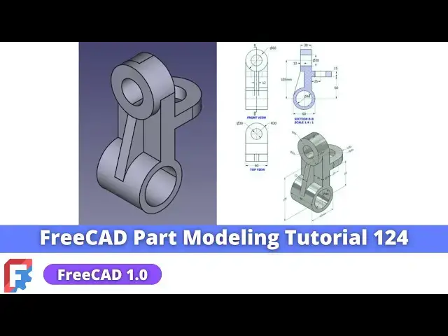
In this video I have explained How to Model Part in FreeCAD with the help of part design Workbench.
▶️ Visit my website for more info on FreeCAD-:
https://mechnexus.com/
▶️ Get my FreeCAD Crash Course for beginner-:
https://www.udemy.com/course/freecad-course-for-beginner/?referralCode=3BA9B526A12F96295D44
▶️ Download Source File of Tutorial-:
https://mechnexus.com/mechnexus-youtube-tutorial-source-file/
▶️ Buy Me a Coffee
I am very grateful that you watch my videos and I am constantly trying to improve the quality of the videos on this channel. If you'd like to help me do this, please consider supporting me so that I can to continue to produce content for your enjoyment.
👉 Help support this channel by buying me a coffee: https://ko-fi.com/mechnexus
All donations will be used to purchase equipment to improve my productivity and increase the quality of the content that I produce. Your kind support will help to grow this channel. Even if it's just enough to buy me a coffee every little helps and this will be repaid in full through my sharing of knowledge.
Show More Show Less View Video Transcript
0:00
Hello friends welcome to Free tutorial
0:03
number
0:04
124 and in this tutorial we will model
0:07
this part and as you can see that I have
0:10
already model it and I will show you
0:13
from the scratch how you can do the same
0:16
to model this part I have a free CAD 1.0
0:21
it is a
0:23
1.0
0:25
rc2 so if you have not the fread 1.0
0:31
install
0:32
it and uh let's begin our tutorial so I
0:38
will close this file and create a new
0:41
file so here I have created a new file
0:44
and first thing which I will do is to
0:46
insert my body and I will press the
0:49
space bar and on my origin plane and I
0:52
will select this right plane and click
0:55
on the
0:56
sketch and uh off this origin plane
1:00
and now we will uh read our drawing so
1:03
inside diameter is of 44 and outside
1:07
diameter is of 60 so
1:10
here I will create two
1:15
circles and uh select the dimension
1:19
tool provide the outer diameter is of 60
1:24
mm and inner diameter is of 44
1:31
and uh I will move this
1:34
Dimension to the this side because we
1:37
will create a sketch profile here so we
1:41
will select a rectangle tool and uh
1:45
create a
1:50
rectangle we will delete this
1:57
line and we will use the trim tool
2:06
to trim
2:07
it and
2:10
now we will uh give the dimensions so
2:13
first I will select this point and this
2:16
point and uh provide the vertical
2:22
relation and from Center to this point
2:26
is of 135 so I will select Dimension to
2:30
tool
2:31
and provide the dimension of
2:36
135 and this one is of uh
2:41
20 freet 1.0s dimensioning method is
2:46
like the solid works where it
2:48
automatically detect whether it is a
2:50
horizontal Dimension or vertical
2:52
Dimensions you can specifically select
2:56
the dimension you want and here is the
2:58
shortcut which you
3:01
can use it so here our sketch is fully
3:06
constraint so we will come out of the
3:09
sketch and we will extrude it to the
3:12
distance of a 60 mm so we will select
3:15
the sketch click on
3:17
extrude and here we will provide the
3:20
value 60 mm and click on the symmetric
3:23
to the plane click on
3:25
okay press
3:27
zero for isometric View and here we will
3:33
provide the radius of 30 mm so I will
3:38
select the fillet
3:40
tool select this hede and this age so
3:44
here is a fillet of uh
3:48
R30 so we will provide
3:55
29.99 and click on okay
4:01
now our next feature is to add a
4:04
material at this portion so we will
4:06
select this phas and click on the
4:11
sketch click on uh project geometry and
4:15
project this radius and we will create a
4:19
circle equal to this
4:23
radius and we will come out of
4:27
it select the sketch click click on the
4:31
pad the value is of 10
4:34
mm click on
4:39
okay to create this rip to create this
4:43
rip first thing which we will do is to
4:46
create a datm plane so we will on our
4:50
origin plane and we will select this
4:52
exit plane and from here we will create
4:55
a datm
4:58
plane and in a z
5:01
directions we will uh provide the value
5:04
of 30
5:08
mm now we will switch to the right view
5:11
so we can see that our datm plane is
5:14
exact tangent to this
5:16
diameter as this rib is a tangent to
5:20
this diameter now uh we will off the
5:23
origin plane and uh
5:26
rebuild this datum plane
5:29
and uh we will press zero for isometric
5:33
we will select this Statum plane and
5:35
click on the
5:36
sketch and uh we will off this Statum
5:40
plane and from here we will uh switch to
5:43
the flat
5:47
lines and
5:50
now we will uh project this diameter so
5:55
click on the project tool and project is
6:01
diameter and here we will uh create a
6:06
rectangle and from here we will uh
6:09
switch to the
6:11
wireframe we will select it and delete
6:14
and uh here we will uh use the trim tool
6:18
to trim this point and select the arc
6:23
tool and create an arc and now we will
6:28
make this symmetric so we will click on
6:30
the symmetricity select this point this
6:34
point and this
6:40
axis press contrl
6:42
Z instead of that we will make this uh
6:46
symmetric this Quantom Point select this
6:50
this and this axis and this is off a 12
6:53
mm so we will provide the value of uh 12
7:00
mm and
7:08
now we will switch to the flat
7:18
lines yes
7:23
now we will select this line and this
7:28
point
7:31
and add a coincidence
7:36
relation and we will come out of the
7:40
sketch extrude it to the distance of uh
7:44
up to this phase so we will select the
7:46
face tool and select this face and you
7:50
can see that material is also added
7:53
inside so no issue we will click on
7:57
okay and now
8:02
we will uh select this face and click on
8:05
the
8:06
sketch and uh click on the project
8:10
geometry project it and uh from here we
8:14
will uh switch to the
8:18
wireframe and we will click on a circle
8:21
tool and create a circle select this and
8:25
this and made it
8:28
equal click on on
8:32
okay and uh we will switch to the flat
8:36
lines and we will remove the
8:51
material select the sketch click on exro
8:56
Cut and from here say it through all say
9:01
okay and
9:07
now we will press zero for isometric and
9:11
we will remove the
9:13
material so we will select the face and
9:16
click on the
9:19
sketch click on Project geometry and
9:22
project this
9:25
age and project this s
9:31
switch to the
9:33
wireframe and we will also project this
9:37
H now we will select a line
9:42
tool create a
9:44
line select this and this and uh add a
9:49
tangent select the trim tool and trim
9:56
it and now select a 3o
10:00
Arc create an
10:08
arc select this and this s and made it
10:15
equal and
10:19
now select line
10:23
tool and close the
10:28
profile now close
10:34
it and here what we will do we will
10:36
select this line and made it
10:41
construction and we will select a line
10:49
tool and from here we will switch to the
10:54
wireframe and join
10:57
it and now
11:01
we will uh provide this very approximate
11:05
value let's
11:08
say5
11:11
mm and now we will close
11:14
it and from here we will uh switch to
11:17
the flat lines so now you can see that
11:21
uh material has been completely
11:26
removed and now
11:30
we will uh create this pad so for this
11:34
we require a data plane and which is of
11:38
60 mm so we will on our origin plane and
11:42
we will select this
11:48
plane and
11:51
uh create a data
11:55
plane and provide the value 60 mm
12:01
click on
12:03
okay
12:05
now off the origin plane and on the datm
12:08
plane rebuild it select the datm plane
12:11
and click on the
12:16
sketch and we will off the datm plane
12:20
and switch to the
12:26
isometric and here
12:30
we will click on the project
12:37
geometry and we will create a rectangle
12:40
profile so switch to the top view switch
12:44
to the
12:46
wireframe select the
12:51
rectangle select the line and this
12:54
point and made it coincidence
13:00
select this line and add a dimension of
13:04
55
13:07
mm and now we will uh extrude this
13:10
profile to the 15
13:13
mm we will close our
13:23
sketch and we will select the sketch
13:27
click on extrude
13:31
click on
13:34
reverse so here one thing which we have
13:38
to understand is that we need to on our
13:43
datm plane
13:45
and we need a
13:49
material upper side of this dat temp
13:51
plane so click on the
13:54
pad so here we will provide the 15 mm
13:59
click on
14:01
okay select the DAT temp plane and off
14:04
it and now we will uh provide the
14:08
fillet of uh 30
14:11
mm
14:12
because
14:16
here is of R30 is given so we will uh
14:21
select this age and this age and click
14:24
on the fet and provide the value 29.9
14:30
9 and click on
14:33
okay now we will move to the next
14:36
feature which is to create a hole at uh
14:40
this
14:42
location so select the face and uh click
14:45
on the
14:49
sketch we will click on the project
14:53
geometry select the circle
14:59
and this is the diameter 30 which we can
15:03
see here you can also make with uh whole
15:07
features but make sure that uh uh drill
15:11
30 size drill is available in the market
15:13
so I'm not going to make with a hole and
15:17
I will make it through the material
15:19
removal process which is the pocket tool
15:21
so simply I will give here diameter
15:25
30 click on okay select the
15:30
pocket and here simply I will say
15:32
through all click on okay now we will
15:37
move towards the next feature which is
15:40
to again create a
15:42
hole on this face so we will select the
15:45
ph and click on the sketch and this hole
15:50
is also 30 mm so click on the project
15:52
geometry and project it so that we get a
15:55
Center Point select the circle create a
15:59
circle select
16:01
diameter and provide the 30
16:05
mm click on
16:07
close click on
16:13
pocket click on through all say
16:16
okay so we have successfully created the
16:19
whole and this also complete our
16:24
model so this is all about how we have
16:28
have uh did the part modeling tutorial
16:32
number
16:33
124 I hope you have enjoyed this
16:36
tutorial thank you for watching and
16:39
thank you for your valuable time
#CAD & CAM