Up next in 10

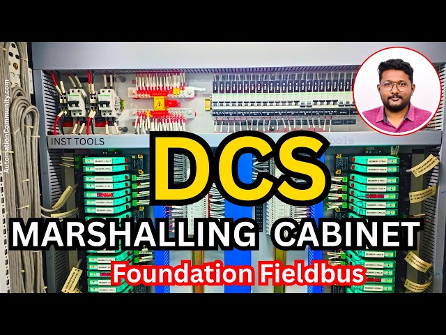
In this video, you will learn about the Foundation Fieldbus DCS marshalling cabinet and its role in interfacing field segments with the DCS control system. It explains how signals are organized, terminated, and routed within the DCS marshalling cabinet, along with practical insights from industrial installations.
👉 Get Full Fieldbus Course Here: https://learn.automationcommunity.com/courses/foundation-fieldbus-course/
✨ FOLLOW US ✨
👉WhatsApp: https://whatsapp.com/channel/0029VaAbUecLNSa4rDPOV31o
👉Telegram: https://t.me/+u3qORX5FKec1NjA1
👉LinkedIn: https://www.linkedin.com/company/instrumentationtools/
👉Facebook: https://www.facebook.com/instrumentationtoolss/
👉Instagram: https://www.instagram.com/instrumentationtools/
👉YouTube: https://youtube.com/instrumentationtools?sub_confirmation=1
👉JOIN Courses: https://automationcommunity.com/
#marshalling #DCS #tutorial
Tags:
dcs marshalling cabinet explained, foundation fieldbus marshalling cabinet, fieldbus marshalling wiring, signal termination marshalling cabinet, field to control room wiring dcs, fieldbus segment routing cabinet, industrial marshalling panel design, control system cabinet wiring, instrumentation signal routing dcs, junction to system cabinet integration, process automation wiring practices, fieldbus cabinet layout, industrial automation training fieldbus
Show More Show Less View Video Transcript
0:07
Hello everyone. Myself Bharadwaj. In the
0:11
previous video, we discussed about
0:14
overview of the Foundation Fieldbus
0:17
network from the field to control
0:20
system.
0:22
In this video, I will discuss in detail
0:26
about the marshalling cabinet related to
0:30
Foundation Fieldbus.
0:32
First, we will see this field junction
0:34
box again. So, this is our Foundation
0:37
Fieldbus junction box.
0:39
From the junction box, we will receive
0:41
two pair cable. In the two pair cable,
0:44
we need one pair cable. The second one
0:48
is for backup purpose,
0:51
spare purpose.
0:52
So, this is our
0:54
junction box, right?
0:56
Where is our trunk cable?
0:58
So, this is our trunk cable
1:01
coming from the junction box and going
1:03
to the
1:04
marshalling cabinet in the control room.
1:08
If you see the color code of this trunk
1:11
cable, it is brown
1:14
and blue color.
1:16
Just remember this color coding.
1:19
This brown and the blue color wires are
1:22
available inside this orange color
1:25
cable, see?
1:26
Foundation Fieldbus, we are using orange
1:29
color cables. Okay, like these cables.
1:32
Inside these orange color cables, we
1:34
have
1:36
the brown and the blue color wires.
1:41
Now, I will go to the marshalling
1:42
cabinet.
1:44
See, this is the marshalling cabinet
1:46
which is installed in the control room.
1:51
First, we will see the available
1:52
components and wiring connections.
1:56
See,
1:57
these are the cables coming from the
2:00
junction boxes.
2:02
That means these are trunk cables. See,
2:06
trunk cables from field junction boxes.
2:09
These are entered here.
2:11
And then, these cables will go through
2:13
this duct
2:16
and it will go to
2:18
surge protection device.
2:21
We know that we have to install surge
2:24
protection device at both ends. That
2:27
means in the field and in the control
2:30
room.
2:31
Because Foundation Fieldbus networks are
2:35
very sensitive to the uh lightning
2:37
strikes or electrical surges.
2:40
That is why this is very important
2:42
component.
2:43
During any lightning strike or uh any
2:46
unwanted high voltages, this will
2:49
protect the
2:50
Fieldbus modules.
2:53
After surge protection device, the cable
2:56
will go to
2:58
Fieldbus
3:00
power hub
3:01
or motherboard. So, these are the
3:03
Fieldbus
3:05
power hubs or motherboards.
3:08
These boards will provide the power
3:09
supply to the junction boxes and then,
3:13
it will go to the respective field
3:15
instruments.
3:16
And also, these will provide the
3:19
communication signals path between
3:22
our Link Active Scheduler, nothing but
3:24
Foundation Fieldbus cards, and the
3:28
field instruments via junction boxes.
3:32
And then, from the
3:34
Fieldbus power hub or motherboard
3:36
module,
3:38
the interface cables,
3:40
see, these are the cables.
3:43
These interface cables will go to the
3:45
system cabinet.
3:47
See, these are the cables going out from
3:49
this marshalling cabinet and they will
3:52
go to the system cabinet. And then,
3:54
these will be connected to
3:56
Foundation Fieldbus related modules.
4:00
So, this is the overview inside the
4:03
marshalling cabinet. If you see these
4:06
Fieldbus power hubs needs power supply,
4:09
right? That is why at the top, we have
4:12
MCBs.
4:14
And uh next, we will see the high
4:16
resolution pictures so that you will get
4:19
clear idea.
4:20
Now, you understand the signal flow from
4:24
the field instruments, that means from
4:26
the junction boxes.
4:27
We will get one pair cable, that is the
4:30
trunk cable.
4:31
And the cable will be entered
4:33
here in the panel and then, it will go
4:36
and connect to the surge protection
4:38
device.
4:40
And from the surge protection device,
4:41
the cable will go and connect to the
4:44
respective Fieldbus power hub or
4:46
motherboard.
4:48
And then, from the Fieldbus power hub,
4:50
one interface cable will go and connect
4:53
to the respective Foundation Fieldbus
4:55
module.
4:57
I'm just repeating again so that you
4:59
will understand it clearly.
5:01
Now, let us see each of these parts
5:03
inside this marshalling cabinet with
5:05
high resolution images
5:07
so that we will have some better
5:09
clarity.
5:11
See,
5:13
what is the color code? The brown and
5:16
the blue. These are the wires inside the
5:19
trunk cable. See, these are the cables
5:22
coming from the
5:24
junction boxes.
5:26
So, this is one cable. This is second
5:27
cable. Each have two pair cable.
5:31
We are using only one pair. The second
5:33
one is spare.
5:35
See, this is one cable. That means this
5:37
is one junction box. This is second
5:39
junction box. This is third, fourth,
5:42
fifth, sixth, seventh, eighth, ninth,
5:45
10th.
5:46
In one line, we have 10 junction boxes.
5:49
Let's say each junction box is connected
5:52
with 10 instruments.
5:55
Then,
5:56
these 10 cables are carrying 10
5:58
multiplied by
6:00
10
6:02
100 instruments.
6:05
If each junction box is connected with
6:07
15 instruments,
6:09
then, these 10 cables are carrying 150
6:13
instruments related data
6:16
from the field to the control system.
6:19
So, when you compare this setup with the
6:22
4 to 20 milliampere or HART protocol
6:25
based instruments, then, you can easily
6:28
say that the wiring is reduced.
6:32
So, this is one of the major advantage.
6:34
Remember that.
6:36
As simple as that. Let's say if you have
6:38
30 field junction boxes, then you will
6:41
receive 30 number of cables from the
6:44
field to the panel.
6:47
These cables are dressed like this and
6:49
they will enter into the duct, right?
6:52
These are the cables going to the duct.
6:55
Now, let us see the next one. The cables
6:56
are going and connecting to a surge
6:59
protection device.
7:00
So, the cable is
7:02
uh connected to the These are the surge
7:04
protection devices.
7:07
Each junction box have one dedicated
7:10
surge protection device.
7:13
The cable have two wires, the brown and
7:16
the blue, right? You can see here.
7:19
The brown and the blue.
7:22
The brown and blue are connected to one
7:24
end, input side of this surge protection
7:26
device. You can see the in,
7:28
right?
7:29
And the out will go and connect to a
7:34
Fieldbus power hub or motherboard. You
7:37
can see it here. In is entered here and
7:40
out. What is the color code here?
7:42
Remember, the red color and the blue
7:45
color.
7:46
These are the internal cables between
7:48
surge protection device and Fieldbus
7:50
power hub.
7:52
So, let us see the Fieldbus power hub.
7:54
See, this is the Fieldbus power hub and
7:56
this is the surge protection device.
7:59
From the surge protection device, the
8:00
cable will come and connect to this
8:03
Fieldbus power hub. If you see in this
8:05
model, in this one Fieldbus power hub,
8:09
we have total four segments.
8:12
See, this is segment one, segment two,
8:15
segment three, segment four.
8:18
In the previous videos, we already
8:20
discussed that in Foundation Fieldbus,
8:23
the terminology for each trunk cable or
8:27
for each communication network, that
8:30
means the instruments connected to one
8:32
junction box is called a segment.
8:36
If you have, let's say, three junction
8:38
boxes, then you have three segments.
8:40
Segment one for first junction box,
8:43
the segment two for second junction box,
8:45
like that.
8:46
In one Fieldbus power hub, see, you can
8:49
see it here.
8:51
Fieldbus power hub or Fieldbus
8:53
motherboard.
8:56
In one Fieldbus power hub, we have four
8:59
segments.
9:00
You can see the label here, segment one
9:03
PSU L.
9:05
Segment one PSU R. That means power
9:08
supply unit left, power supply unit
9:11
right.
9:12
These two provides the power supply to
9:15
the Foundation Fieldbus junction box.
9:19
So, segment one is for one junction box.
9:22
We have two power supply modules.
9:25
We have the backup. We have the
9:27
redundancy. If one fails, it will not
9:29
affect all instruments connected to a
9:32
junction box. That is why two are given
9:34
here. So, the segment one, the left and
9:37
right providing power supply to the
9:40
single junction box. So, from the surge
9:43
protection device, the cable will come
9:45
and connect to the
9:47
here.
9:48
You can see here how many terminals are
9:50
available.
9:52
This is
9:53
one set, second set, third set, and
9:55
fourth set. That means
9:57
this is the trunk cable coming from one
9:59
junction box.
10:01
And this is the trunk cable coming from
10:03
second junction box.
10:05
This is the trunk cable coming from
10:07
third junction box and fourth junction
10:09
box. You can also call it a segment one,
10:11
segment two, segment three, segment four
10:15
in this fieldbus power hub.
10:18
You can also see that there is one
10:20
dedicated on and off switches available
10:23
here, right?
10:25
So,
10:25
you can
10:27
uh if you want to make it offline, then
10:29
you can turn it off.
10:31
Generally, for working cases, it should
10:33
be in on state.
10:35
You can see the status of the modules
10:37
here, the healthiness status.
10:40
So, segment one, segment two, segment
10:42
three, and segment four.
10:45
If you see in between, there is another
10:47
extra module.
10:49
This is diagnostics module. See?
10:53
What it is called? Fieldbus diagnostic
10:55
module basic version. There are
10:58
different versions of this module
11:00
available, basic version, advanced
11:02
version, like that.
11:04
So, as per your design, the type of
11:06
module will be decided.
11:09
This module provides the diagnostics
11:11
information like healthiness status of
11:13
your communication bus
11:15
or healthiness status of your devices.
11:18
If any problems are there, these things
11:20
will be reported by this module.
11:23
And it will be connected to your plant
11:26
resource manager, that is a server in
11:28
Yokogawa DCS system.
11:31
If you configure this with your plant
11:33
resource manager, in that software, you
11:36
can view the diagnostics of your
11:37
foundation fieldbus networks.
11:40
If you see here,
11:42
this one power hub, it has two
11:46
connectors. See? This side.
11:48
This is connector one. This is connector
11:51
two.
11:52
Nothing but interface cable one,
11:54
interface cable two.
11:56
These two cables will go from this
11:59
marshalling cabinet and it will connect
12:01
to the
12:03
fieldbus modules
12:05
installed in the system cabinet.
12:08
Why two are required?
12:10
Let's say this power hub supports how
12:13
many channels or how many segments? Four
12:15
segments.
12:16
Let's say I have 15 instruments
12:19
connected to each segment. Then how many
12:22
instruments are connected to this
12:23
fieldbus power hub?
12:25
4 * 15, that means 60 instruments are
12:29
handled by this power.
12:31
If I have only one connector cable going
12:33
from this fieldbus power hub to the
12:35
system cabinet, then it is very, very
12:37
risky.
12:38
If there is some problem with one cable,
12:40
then all 60 instruments will be down.
12:44
Then it is a major problem for your
12:46
plant. That is why minimum two are
12:48
connected. This is connector one and
12:51
this is connector two.
12:52
That means for each uh fieldbus power
12:56
hub, we have two individual fieldbus
12:59
modules.
13:01
So, this cable will go and connect to
13:03
one fieldbus module and the second one
13:07
will go and connect to the second
13:08
fieldbus module.
13:10
If there is any problem with the first
13:11
one, the second one will take care.
13:15
And if you see, we already discussed it
13:17
previously that
13:19
there are two terminators
13:22
in your network. One is installed at the
13:24
field side, and the second one is
13:26
installed in the panel.
13:28
It can be a separate dedicated
13:30
terminator.
13:32
Otherwise, in some models, power supply
13:34
unit inbuilt also,
13:36
it is integrated.
13:38
That means in this power supply module,
13:40
we have terminator already installed.
13:44
That is why you do not found any
13:46
external device.
13:49
That depends on your model.
13:51
You see here,
13:53
these two.
13:54
These two are the
13:56
power supplies for this fieldbus power
13:59
hub. 24 volts DC power supply. This is
14:02
primary power supply. This is secondary
14:04
power supply.
14:05
Two power supplies are minimum
14:08
because this one power supply provides
14:11
again power to 60 instruments. This is
14:15
the power source providing power to this
14:17
motherboard.
14:18
And this motherboard is providing power
14:20
to four junction boxes. So, if there is
14:23
any problem with one power supply, then
14:25
all 60 will be down.
14:27
That is why minimum power supplies must
14:30
be two, primary and secondary.
14:34
Similarly, we have two communications
14:35
here internally.
14:37
This is one and this is two.
14:41
So, this is our fieldbus
14:43
power hub.
14:45
And you can see another picture of the
14:47
marshalling cabinet.
14:49
See?
14:51
These are the surge protection devices
14:53
and these are also surge protection
14:54
devices. And these are the
14:57
fieldbus power hubs.
15:00
And at the top, we have MCBs for the
15:02
power supply and busbar and again single
15:06
pole MCBs for controlling the power
15:07
supply to the
15:09
individual fieldbus motherboards. So,
15:12
these are the interface cables. See?
15:15
On the panel left side, it is
15:18
uh dressed like this.
15:22
And I will show you one more
15:25
I miss. See?
15:26
You see this fieldbus power hub?
15:29
You can see here this diagnostic module,
15:32
there is some indication. You can see
15:34
here, we have segment one. Total four
15:37
LEDs are available here on this
15:40
diagnostic module.
15:41
Segment one, segment two, segment three,
15:44
segment four.
15:46
So, segment three LED is on. That means
15:49
there is some issue with the segment
15:51
three.
15:52
There may be a complete communication
15:54
issue or some instruments maybe some
15:56
issue is there. Remaining may work
15:57
perfectly.
15:59
It depends. You have to troubleshoot the
16:01
network and devices connected to the
16:03
network.
16:04
Then you will know the status.
16:08
See, this is also having primary power
16:10
supply, secondary power supply.
16:14
And see here.
16:16
Here.
16:17
These are alarms. You can configure a
16:19
digital input so that you will have some
16:22
alerts on your screen.
16:24
You can take individually for the
16:26
fieldbus power hub or you can loop for
16:28
complete power hubs as per your
16:30
requirement.
16:31
In our case, it is looping is done. See?
16:34
One fieldbus power hub to another
16:36
fieldbus power hub. That means we are
16:38
taking common alarm instead of
16:40
individual alarm to save the IOs as per
16:43
your design.
16:46
See?
16:48
The status inputs.
16:50
Alarm status, common alarm.
16:53
So, this is about marshalling cabinet.
16:56
Very easy, right?
16:59
The cable entered from the field
17:01
connected to surge protection device.
17:03
From here, it is going to fieldbus power
17:06
hub or motherboard. And from the
17:09
fieldbus power hub,
17:10
the cable will go from here to this
17:13
system cabinet. See?
17:15
These are the cables going out.
17:19
So, that's it.
17:20
This is all about the
17:23
marshalling cabinet.
17:26
If you have any questions, please let us
17:28
know.
17:29
And thank you. I will meet you in the
17:32
next video. Do like our videos, share
17:35
our courses with your colleagues and
17:37
friends.
17:38
Thank you for your
17:40
support.