videocam_off
This livestream is currently offline
Check back later when the stream goes live
Up next in 10

Aircraft Fuel Systems Explained | From Light Aircraft to Jet Transports & Helicopters
In this video, we explore aircraft fuel systems across a wide range of aircraft types—from small single-engine airplanes to large jet transport aircraft and helicopters.
You’ll learn how fuel is:
• Stored, vented, and protected
• Delivered at the correct pressure and flow
• Managed in gravity-feed, pump-feed, and fuel-injection systems
• Safely supplied during all phases of flight
•
The video covers:
• Fuel system requirements
• Fuel storage and refueling systems
• Types of aviation fuel (AVGAS and Jet Fuel)
• Small single-engine aircraft fuel systems
• Gravity-feed and pump-feed systems
• Fuel-injected aircraft
• Large reciprocating aircraft (DC-3 example)
• Jet transport aircraft fuel systems (with fuel jettisoning)
• Helicopter fuel systems
Show More Show Less View Video Transcript
0:07
The aircraft fuel system plays a
0:09
critical role in safe and efficient
0:11
flight. Its purpose is simple but vital
0:14
to store fuel and deliver the correct
0:16
amount of clean fuel to the engine at
0:18
the proper pressure. In this video, we
0:20
will study aircraft fuel systems step by
0:23
step, beginning with fundamental
0:25
concepts and progressing toward
0:26
practical aircraft applications.
0:31
The aircraft fuel system is designed to
0:33
store fuel and supply it to the engine
0:35
under all operating conditions. It must
0:38
function reliably during engine start,
0:40
taxi, takeoff, climb, cruise, descent,
0:44
and landing. The system must continue to
0:47
operate despite changes in altitude,
0:49
aircraft attitude, acceleration, and
0:52
atmospheric conditions. Every aircraft
0:55
fuel system must be designed to deliver
0:57
fuel at the correct pressure and flow
0:59
rate. So the engine and auxiliary power
1:01
unit operate properly in all normal and
1:04
certified flight conditions, including
1:06
maneuvers. To maintain safe operation,
1:09
each fuel pump is designed to draw fuel
1:11
from only one tank at a time, and the
1:14
system must prevent air from entering
1:16
the fuel lines. For turbine powered
1:18
aircraft, fuel systems must meet strict
1:21
fuel venting requirements and continue
1:23
operating even if the fuel contains
1:26
small amounts of water. The engine must
1:28
keep running under icing prone
1:30
conditions, ensuring reliability
1:32
throughout the full range of fuel flow
1:34
and pressure.
1:36
Each fuel system must be designed and
1:38
arranged to provide independence between
1:40
multiple fuel storage and supply systems
1:43
so that failure of any one component in
1:46
one system will not result in loss of
1:48
fuel storage or supply of another system
1:51
to prevent fire hazards. Fuel systems
1:54
include lightning protection. They are
1:56
built to prevent ignition caused by
1:58
lightning strikes, electrical discharge,
2:00
corona effects, or streamering near fuel
2:03
vents.
2:04
Pilots must be able to accurately
2:06
determine the amount of usable fuel on
2:08
board and receive an uninterrupted
2:10
supply when the system is operated
2:13
correctly. The fuel system must also
2:16
safely isolate or retain fuel during all
2:18
operating conditions and reduce risks to
2:21
occupants during survivable emergency
2:23
landings.
2:25
The fuel storage system includes the
2:27
aircraft's fuel tanks and their
2:29
supporting structure. These tanks are
2:31
built to withstand flight loads and are
2:33
isolated from crew and passenger
2:35
compartments for safety. They are
2:37
protected against heat and environmental
2:39
damage and they store enough fuel to
2:41
ensure safe operation under all expected
2:43
conditions. On larger aircraft, the
2:46
system may also include fuel jettisoning
2:48
which allows excess fuel to be safely
2:51
dumped to reduce landing weight.
2:54
Fuel refilling or recharging systems
2:56
allow fuel to be safely added to the
2:59
aircraft. These systems may use gravity
3:01
fueling or pressure fueling. They are
3:04
designed to prevent incorrect fueling,
3:06
fuel contamination and hazards to ground
3:09
personnel and the aircraft.
3:11
Each aircraft engine is designed to
3:13
operate on a specific type of fuel and
3:16
only the manufacturer approved fuel may
3:18
be used. Mixing fuels is not permitted
3:21
as it can lead to serious engine damage
3:23
or failure. Aviation fuels are broadly
3:26
classified into two main categories.
3:29
Aviation gasoline known as AV gas is
3:32
used in reciprocating piston engines and
3:34
is highly volatile for proper
3:36
combustion. Jet fuel also called turbine
3:39
fuel is used in turbine engines and has
3:41
lower volatility with a higher flash
3:43
point making it safer for high
3:45
temperature operation. Using the correct
3:48
fuel ensures proper engine performance,
3:50
reliability and flight safety. Small
3:53
single engine aircraft use different
3:55
fuel system designs. The layout depends
3:58
on fuel tank location, such as high-wing
4:00
or low-wing aircraft, and how fuel is
4:03
delivered to the engine. Carbbureted
4:05
engines use a different fuel system than
4:07
fuel injected engines.
4:10
The simplest fuel system is the gravity
4:12
feed system, commonly found on small
4:14
high-wing training aircraft. These
4:16
aircraft typically have two fuel tanks,
4:19
one in each wing. Fuel flows by gravity
4:22
from the tanks to the engine without the
4:24
need for a fuel pump.
4:26
The outlets of both tanks are connected
4:28
to a fuel selector valve which allows
4:30
the pilot to select left tank, right
4:33
tank, both tanks or fuel off. When the
4:36
both position is used, fuel from both
4:39
tanks feeds the engine simultaneously.
4:41
Because both tanks can feed the engine
4:43
at the same time, the space above the
4:45
fuel in both tanks must be
4:47
interconnected and vented to the outside
4:49
atmosphere. The vent line usually exits
4:52
on the underside of the wing where fuel
4:54
siphoning is unlikely. After leaving the
4:57
selector valve, fuel flows through the
4:59
main fuel strainer which removes dirt
5:01
and water. From the strainer, fuel flows
5:04
directly to the carburetor inlet. Fuel
5:07
for the engine primer system is also
5:09
taken from the main strainer.
5:12
Low-wing aircraft cannot rely on gravity
5:14
to supply fuel to the engine. So, fuel
5:17
pumps are used to provide the required
5:19
pressure. These systems typically
5:21
include an engine-driven fuel pump and
5:23
an electric fuel pump for backup. The
5:25
fuel selector valve usually allows
5:27
selection of the left tank, right tank,
5:29
or fuel off, but it does not include a
5:31
both position. This prevents the pump
5:34
from drawing air if one tank runs empty.
5:36
After passing through the selector
5:38
valve, fuel flows through the main
5:40
strainer and then to the electric fuel
5:42
pump. The electric pump and engine
5:44
driven pump are installed in parallel,
5:46
allowing either pump to supply fuel
5:48
independently. Before engine start, the
5:51
electric pump is switched on to check
5:53
fuel pressure. After start, it is turned
5:55
off to confirm the engine-driven pump is
5:58
operating. The electric pump is used
6:00
during engine start as a backup in case
6:02
the engine driven pump fails and to
6:04
maintain fuel flow while changing tanks.
6:08
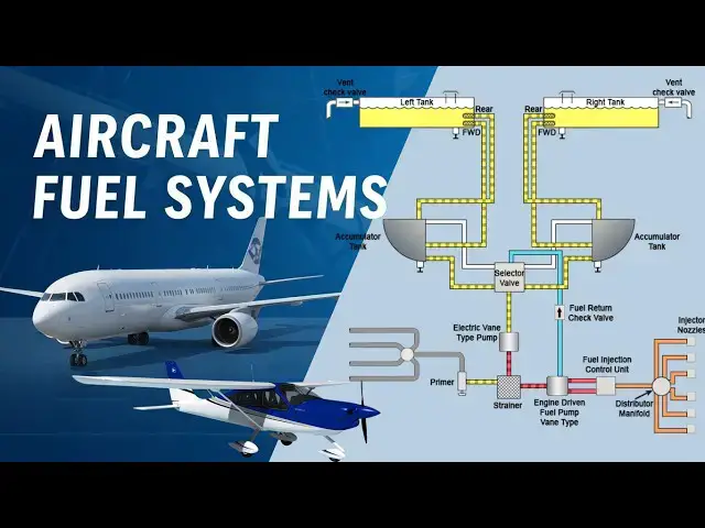
In high-wing aircraft equipped with a
6:10
fuel injection system, such as the
6:12
Teladine Continental system, a portion
6:14
of the fuel is continuously returned to
6:17
the fuel tanks. This returned fuel
6:19
carries fuel vapors with it, helping to
6:21
prevent vapor lock and ensuring smooth
6:24
engine operation. Fuel flows by gravity
6:26
from the wing tanks through front and
6:28
rear feed lines into small accumulator
6:31
or reservoir tanks. From the bottom of
6:34
these reservoirs, fuel is directed to
6:36
the fuel selector valve. The selector
6:38
valve not only routes fuel to the
6:40
engine, but also directs separated fuel
6:43
vapors back into the vent space of the
6:45
selected reservoir tank. An electric
6:47
auxiliary fuel pump then pushes the fuel
6:50
through the strainer and supplies it to
6:52
the engine-driven fuel pump. From there,
6:54
fuel flows to the fuel control unit,
6:57
which precisely meters the amount
6:58
required by the engine. Any excess fuel
7:01
is returned to the pump inlet while
7:03
vapor laden fuel is routed back to the
7:05
tanks maintaining proper pressure and
7:08
preventing fuel vapor formation in the
7:10
system.
7:11
Many small multi-engine aircraft are
7:14
equipped with the RSA fuel injection
7:16
system. Unlike the Teladine Continental
7:19
system, this design does not return
7:21
excess fuel to the tanks. Each wing
7:23
contains two interconnected fuel tanks
7:26
that function as a single fuel source.
7:28
Fuel selector valves allow either engine
7:30
to draw fuel from either wing tank, a
7:33
feature known as crossfeed. From the
7:35
selector valve, fuel passes through a
7:37
fuel filter, then an electric fuel pump,
7:40
followed by an engine-driven pump before
7:43
entering the fuel injection system, and
7:45
finally being delivered to the engine
7:47
cylinders. The system is monitored using
7:49
fuel quantity gauges, fuel pressure
7:51
gauges, and fuel flow indicators. Fuel
7:54
flow is measured by a differential
7:56
pressure gauge and displayed in gallons
7:58
per hour or pounds per hour.
8:01
Large multi-engine aircraft powered by
8:03
reciprocating radial engines such as the
8:05
DC3 are no longer produced, but many are
8:09
still in service. These aircraft
8:11
typically use carbureted engines and
8:13
fuel systems similar to those found in
8:15
smaller aircraft. In the DC3, each
8:18
engine has a selector valve that allows
8:20
fuel to be drawn from either a main or
8:23
auxiliary tank. Fuel flows through a
8:25
strainer to an engine-driven pump and
8:27
then to the carburetor. A cross- feed
8:30
system allows one engine to supply fuel
8:32
to the other if required. Early aircraft
8:35
used a hand operated wobble pump for
8:37
priming, while later models replaced it
8:39
with electric pumps. Fuel pressure is
8:41
monitored through gauges and warning
8:43
lights to alert the crew of any loss in
8:46
pressure.
8:47
Jet transport aircraft use fuel systems
8:50
designed to safely and efficiently
8:52
deliver large quantities of fuel. In
8:54
aircraft such as the Boeing 727, fuel is
8:57
stored in multiple tanks, including
9:00
integral wing tanks and fuselage mounted
9:02
bladder tanks. The wing tanks are built
9:04
into the wing structure itself, while
9:07
fuselage tanks use flexible fuel cells.
9:09
Electric boost pumps in each tank supply
9:12
fuel to the engines and a cross feed
9:14
system allows any tank to supply any
9:17
engine when selected providing
9:19
operational flexibility and redundancy.
9:22
Fueling is accomplished through a single
9:24
point pressure fueling system which
9:26
automatically shuts off to prevent
9:28
overfilling. The same system allows
9:30
controlled defueling when required.
9:33
During flight, fuel may be jettisoned to
9:35
reduce landing weight. Fuel dump systems
9:38
release fuel safely from the wing tips
9:40
while maintaining engine supply and
9:42
proper balance. Dump limit valves ensure
9:45
fuel dumping stops before engine
9:47
operation is affected. We've covered jet
9:49
transport aircraft fuel systems in
9:51
greater detail in an earlier video,
9:54
which you can access using the link
9:55
displayed above.
9:58
Helicopter fuel systems vary in
10:00
complexity depending on the aircraft
10:02
type. Most helicopters use one or two
10:05
fuel tanks located close to the
10:07
aircraft's center of gravity, usually
10:09
near the main rotor mast in the aft
10:11
fuselof. Some tanks are positioned above
10:14
the engine for gravity feed, while
10:16
others rely on pumps and pressure feed
10:18
systems.
10:20
In basic systems, fuel flows from a
10:22
vented tank through a strainer, shutff
10:25
valve, and main filter before reaching
10:27
the carburetor. Light turbine
10:29
helicopters typically use intank
10:31
electric boost pumps that send fuel
10:33
through shutff valves, airframe and
10:35
engine filters, and then to the
10:37
engine-driven fuel pump. These systems
10:39
include vented tanks, electrically
10:41
operated sump drains, fuel pressure
10:44
gauges, and warning switches for filter
10:46
restrictions. Fuel quantity is measured
10:48
using intank fuel probes. Larger
10:51
multi-engine transport helicopters use
10:53
more advanced fuel systems similar to
10:56
those found in jet transport aircraft
10:58
with multiple tanks, crossfeed
11:00
capability, and pressure refueling
11:02
systems.
11:04
In conclusion, aircraft fuel systems
11:07
vary widely depending on aircraft size,
11:09
configuration, and engine type. However,
11:12
all fuel systems share the same goal to
11:15
deliver clean fuel at the correct
11:17
pressure reliably and safely under all
11:20
operating conditions. Understanding fuel
11:23
systems is essential for safe aircraft
11:25
operation and maintenance. Thank you for
11:28
watching.
11:33
[Music]
#Jobs & Education