Up next in 10

Creating a Node-RED Flow Program in the Click PLUS PLC C2-NRED Module
Node-RED is an innovative and powerful tool for connecting hardware devices, APIs, and online services. Regarding industrial automation, the Click PLUS PLC C2-NRED module takes things up a notch by integrating Node-RED, allowing users to create flows via a visual programming interface. Previously, we updated the Click Programming Software to version 3.70. The firmware in the Click CPU and C2-NRED Module were then updated to their latest versions.
We will guide you through creating your first Node-RED flow program in the Click PLUS PLC C2-NRED module. We will read and write information to and from the Click PLC CPU. We will discuss saving and retrieving our flow programs and troubleshooting. Let's get started.
More information can be obtained at our website. This includes all of the links mentioned in this video. https://accautomation.ca/unleash-innovation-node-red-flow-in-click-plc/
00:00 Unleash Innovation: Node-RED Flow in Click PLC
01:11 Accessing Node-RED
02:23 What is Flow Programming?
03:29 Understanding the Node-RED Interface
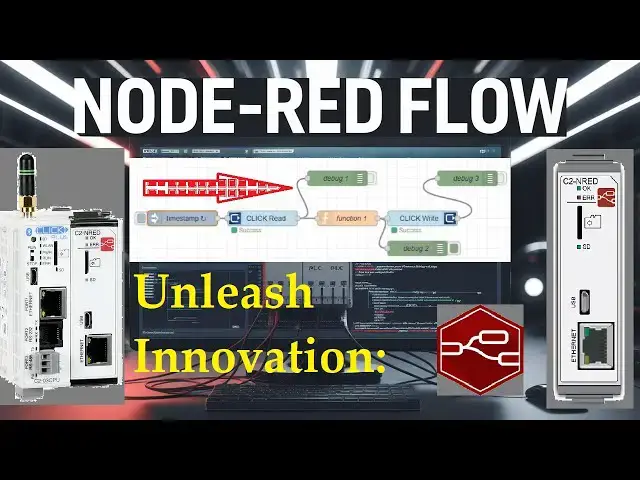
05:09 Building Your First CLICK Read Flow
07:54 Adding A CLICK Write To Our Flow
11:39 Configure The Inject Node
12:22 Saving The Node-RED Flow - Export / Import
Previously, we looked at the following:
Data Logging
https://accautomation.ca/click-plus-data-logging-csv-file-sql-database/
https://youtu.be/ydoWvMzHSKc
Show More Show Less View Video Transcript
0:01
creating a node red flow program in the
0:03
click plus PLC c2n red
0:06
module node red is an Innovative and
0:09
Powerful tool for connecting Hardware
0:11
devices apis and online services
0:14
regarding Industrial Automation The
0:16
Click plus PLC C2 node red module takes
0:19
things up a notch by integrating node
0:21
red allowing users to create flows via a
0:24
visual programming
0:25
interface previously we updated the
0:27
click programming software to version 3
0:30
.70 firmware in the click PLC CPU and
0:34
c2n red module were then updated to the
0:37
latest versions We will guide you
0:39
through creating your first node red
0:41
flow program in the click plus PLC C2
0:44
and red module we will read and write
0:47
information to and from the click PLC
0:49
CPU we will discuss saving and
0:52
retrieving our flow programs and
0:53
troubleshooting let's get started
0:56
detailed information contained in this
0:57
video can be found at ACC automation. CA
1:00
a link has been put in the description
1:01
below if you have not watched the other
1:03
videos yet there are links in the
1:04
description below that will start you a
1:06
video One there'll be links to the rest
1:07
of the videos in the series as
1:11
well accessing node
1:15
red when first applying power to the
1:17
click system with the c2n red module it
1:20
will take up to 45 seconds for the
1:22
module to be booted here's the meanings
1:24
of the lights on the C2 and red card in
1:28
our post click plus c P2 n red easy
1:31
install for PLC module we updated the
1:33
firmware in our click plus CPU to
1:35
version 3.70 and updated the firmware on
1:38
our intelligent module C2 and red we
1:41
then set up the CPU and C2 and red to
1:44
communicate on our
1:48
Network to start and program our node
1:51
red module select open node red from the
1:54
PLC tab of the main menu in the click
1:56
PLC programming
1:58
software select the ethernet option and
2:00
select connect your default browser will
2:03
open up and you will see the node red
2:05
programming screen for the c2n red
2:07
module another way to start the old red
2:10
interface is to start a new tab in the
2:12
browser and paste the URL address and
2:15
port for the programming set copy in the
2:17
C2 and red configuration screen in the
2:20
click DLC programming
2:24
software what is flow
2:27
programming node red may feel un
2:29
familiar to those with experience with
2:31
latter Logic the graphical programming
2:33
language GPL or scripting languages on
2:37
the other hand individuals accustomed to
2:39
scripting languages like JavaScript they
2:40
find lateral logic in a click plus PLC
2:43
quite puzzling each of these three
2:45
languages has its strengths but
2:47
combining them in the click plus C2 and
2:50
red module opens up Innovative
2:52
approaches to Industrial control and
2:54
maker space commercial
2:55
applications node red introduces a third
2:58
type of programming called flow editor
3:01
similar to latter logic this editor is a
3:04
GPL graphic programming language and
3:06
operates like a flowchart where each
3:08
node represents a specific function
3:11
these functions can range from simple
3:12
tasks such as checking a data value to
3:14
more complex operations like calling a
3:16
web server to retrieving a block of
3:18
information behind the scenes node red
3:21
builds a JavaScript application and can
3:23
even incorporate function blocks that
3:25
are JavaScript sub routines
3:28
[Music]
3:30
understanding the node red
3:33
interface the node red interface
3:35
consists of several panels pallet you
3:39
can find nodes to drag onto your
3:41
workspace on the
3:45
[Music]
3:51
left workspace the central area where
3:54
you build your flow
3:58
[Music]
4:08
info panel information about selected
4:11
nose is provided on the
4:13
[Music]
4:20
right help file this area will show you
4:23
two areas the node red help will show
4:26
you changes in the software version and
4:28
you can display the tour as as we did
4:30
before node help you will have all the
4:33
help files for the nodes installed on
4:35
the
4:50
pallet debug panel this area lets you
4:54
view outputs and log messages to help
4:57
debug your flow troubleshooting your
4:59
code becomes easy with a debug
5:01
panel config panel this will help
5:04
configure your flows or specific nodes
5:06
on your
5:09
system building your firstclick read
5:14
flow let's create a simple flow that
5:16
reads inputs from our click plus
5:19
PLC all the pallet NOS can be dragged
5:22
and dropped onto the workspace start by
5:24
dragging an inject mode from the pallet
5:27
to the workplace this node will serve as
5:28
our trigger
5:30
now drag and drop click read and debug
5:32
modes onto the
5:34
workspace the red triangle means that
5:36
there is something not right with a
5:37
setup of this node double click and set
5:39
the address to read our input switches
5:41
on our click plus PLC this is address
5:44
2011 bits 1 to 8 so the size is
5:48
eight you will see that these settings
5:50
are initially in Red so the red triangle
5:53
was shown the memory type can be
5:56
selected for all different click PLC
5:58
areas
6:00
the name that appears on the workspace
6:02
for the node can be changed but we will
6:03
leave this as the default under the
6:06
option tab select show error text show
6:09
error code this will Aid Us in
6:11
troubleshooting our code select done
6:15
none of the nodes now have an error join
6:17
the nodes together by clicking the
6:18
outputs to the inputs start with the
6:20
inject Noe joining to The Click read
6:23
node then the click read node is linked
6:26
to the debug node once everything is
6:28
connected and configured click the
6:30
deploy button this action saves and runs
6:33
your flow a message successful deployed
6:36
will be
6:37
shown select the debug tab on the right
6:40
hand side this will show us the message
6:42
sent from The Click read in the
6:45
debug click on the button in the inject
6:48
node to trigger or flow you should see
6:51
the output in the debug panel this is a
6:53
message object payload expanding the
6:55
message payload you will know we have a
6:57
result data and result text this is all
7:01
the information being sent from The
7:02
Click read node expand the data you'll
7:06
find an array representing all the
7:07
switch conditions we
7:09
requested change the switch State on the
7:12
PLC and Trigger the flow again you will
7:15
now see the updated switch
7:20
[Music]
7:26
conditions selecting the delete all in a
7:29
debug window will clear the debug window
7:31
notice that you will also see the
7:33
success indication Under The Click read
7:35
node this gives us a quick visual that
7:38
indicates their flow is
7:40
working if you're enjoying this video
7:42
please hit the like button keeping up
7:44
with all the latest automation
7:45
Innovations can be difficult so hit the
7:47
Subscribe button remember to click the
7:49
Bell beside your subscription to
7:50
actually receive those
7:54
notifications adding a click right to
7:56
our flow
8:00
dragging a click right node from the
8:01
pallet to our workspace join the click
8:04
read output to The Click right input the
8:07
red triangle on the click right means we
8:09
need additional information for this
8:11
node double click it we will set the
8:13
address to 101 and a size to eight this
8:17
represents the first eight outputs on
8:18
our
8:22
PLC the memory type will show you the
8:24
different areas we can write to in the
8:26
click plc
8:29
[Music]
8:31
under the option tab select show error
8:34
text show error code select
8:38
done drag and drop another debug node
8:41
for the click
8:50
right click the deploy
8:53
button select the injection node for our
8:56
flow we have an error this is despite
8:59
Under The Click right node as well as
9:01
for the debug to the eror is that the
9:04
input payload is not an
9:07
array this is because our output from
9:09
The Click read is more than just an
9:11
array it also contains the result and
9:13
result text we can separate this
9:15
information coming from The Click read
9:17
node by using a function node drag and
9:20
drop a function node onto the
9:22
workspace looking at the debug message
9:24
after the click read you can find the
9:27
path to the data array
9:30
click on the copy path for the
9:32
data double click on the function node
9:36
the on message tab will be displayed we
9:38
can write JavaScript within the function
9:41
node paste our copy path for the data
9:44
array from our click read
9:47
node our JavaScript line will read
9:50
message. payload equals message. payload
9:53
do dat
9:55
semicolon the semicolon at the end of
9:57
the line is necessary for JavaScript
9:59
programming the function node also has
10:02
tabs for setup on start on
10:06
Stop The Help menu will help you with
10:08
how these tabs
10:10
work select
10:13
done join the function node output to
10:16
The Click right input select delete the
10:19
debug 2 node connection and join it with
10:21
the output from the function node add
10:24
another debug node to the output of the
10:26
click right instruction
10:36
deploy the flow ensure the debug area
10:39
window is clear and press the inject
10:42
[Music]
10:45
mode our flow is now working this is
10:48
easily seen by the success under each
10:50
click read and write
10:52
node in a debug window we can see our
10:55
output from debug 2 is now just an array
10:57
of values which then is written into the
11:00
click
11:02
PLC changing the switch inputs on the
11:05
PLC and clicking the inject mode will
11:07
change the
11:10
outputs debug nodes can be turned on and
11:13
off by selecting the output on the Node
11:15
turn off debug one and three from the
11:17
read and write nodes deploy and inject
11:20
the flow we will only see the array red
11:23
and written to our click plus plc
11:40
configure the inject
11:43
node double click the inject node to
11:46
configure it we will leave the payload
11:48
type as a default type
11:51
timestamp we will set the inject time at
11:53
regular intervals this will be the
11:55
frequency of when our flow will function
12:01
select done and deploy our click PLC
12:05
inputs are being read and written every
12:07
0.5
12:08
seconds change the input switches to
12:11
reflect in the click PLC
12:13
outputs remember that we only have an
12:15
end statement in our latter logic code
12:18
node red is doing all the
12:22
control saving the no red flow export
12:25
import
12:29
click the pancake symbol beside the
12:31
deploy button we can now select export
12:33
contrl plus e the export nodes window
12:36
will be displayed we can choose select
12:38
current or all Flows at the windows top
12:42
select current flow and then select
12:46
download this will download a Json file
12:49
of your flow you can rename this file
12:51
for your node red
12:53
program select the export again from the
12:55
menu
13:00
after selecting the nodes for flows that
13:02
we want to save click copy the clipboard
13:05
we can now open any text editing
13:07
software like Windows notepad and paste
13:09
the Json information copied to the
13:11
clipboard
13:37
the import control plusi is used to take
13:39
the Json file and restore your flow or
13:42
flows that have been
13:44
saved
13:46
congratulations you've successfully
13:47
created your first node red flow program
13:50
within the click plus CPU C2 and red
13:53
module to learn more about programming
13:55
with node red click here click here to
13:57
learn more about the click plus PLC this
14:00
is just the beginning you can expand
14:02
your flows by adding more nodes
14:04
connecting to different devices or
14:05
integrating with apis with practice
14:08
you'll unlock the vast potential that
14:09
node red offers for Industrial
14:11
Automation and iot solutions
#Programming