0:00
Hey everyone. On this video guys, I'm
0:01
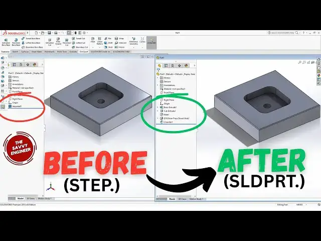
going to be showing you how you can
0:03
convert a step file into SLDPRT file
0:07
format in Solid Works. Okay, but guys,
0:10
before we jump into the details, do not
0:12
forget to hit that subscribe button to
0:14
join the Savvi Engineer community. And
0:16
without further ado, let's jump into the
0:19
video. Okay, so the first thing that I'm
0:21
going to do is to design the piece.
0:23
Okay, and the file format of the piece
0:25
in this case will be SLDPRT.
0:28
I'm going to save it as a step file.
0:30
Okay. Then I'm going to open that step
0:32
file in solid works and extract the
0:34
features and save it as a new SLDPRT
0:39
file format. Okay. So the first step
0:42
will be designing the piece. So in this
0:44
case I'm going to go to the top plan.
0:45
Right click normal two. Right click then
0:48
sketch. I'm going to use the center
0:51
rectangle to draw a rectangle like this.
0:54
So I'm going to use the smart dimension
0:56
to add a 100 mm here and 100 mm here
1:02
also. Then you click on okay. Next I'm
1:05
going to exit the workbench. Then go to
1:08
feters then extruded boss or base. Then
1:11
I'm going to change the value from 10 to
1:13
20. Hit enter. Then okay. Now I'm going
1:18
to go and click on the top face of this
1:21
extrusion. Right click. normal too.
1:24
Right click then sketch. I'm going to
1:26
use the same command center rectangle to
1:29
add a rectangle like this. In this case
1:32
I'm going to add 50 mm as a dimension
1:35
here. And I'm going to do the same thing
1:38
here. 50 mm. Okay. Then you click on
1:41
okay. Exit the workbench.
1:44
Then we go to features. Then you go to
1:46
extruded cut command. In this case I'm
1:49
going to change the value from 20 to 10.
1:51
Hit enter. Then okay again.
1:55
Great. Now I'm going to go and click on
1:58
fillet. I'm going to add a fillet of 10
2:10
here. Then you click on okay.
2:12
Great. Next, I'm going to go and add
2:17
Click here. Then you go and click on
2:19
shamfer. Instead of 10 here, I'm going
2:22
to add one millimeter as a distance.
2:24
Okay. Click on this edge. This edge,
2:29
this one, and this one. Okay. Then you
2:35
Great. Now, I'm going to go and add a
2:37
hole here. Right click normal two. Then
2:41
you go to features. Then you click on
2:44
whole wizard. Okay. I'm going to go and
2:49
Then I'm going to use the center of the
2:51
axis like this. And the diameter of the
2:54
hole will be 10 mm. Okay. Then you click
2:59
Great. So this is a piece created in
3:02
Solid Works. And I'm going to change the
3:05
file format of this piece from SLBRT to
3:09
step. Then I'm going to open that step
3:11
file and extract the features. And I'm
3:14
going to change one of these features
3:16
and save it as a new SLDPRT file format.
3:20
Okay. So now I'm going to go and click
3:26
from part to step AP 214.
3:32
Then you click on save. Great. Okay. So
3:35
now you go and click on open.
3:39
Then you use this option. You click on
3:41
all files. Then you go and search for
3:46
This is the step file part 8. Open.
3:51
Okay. So this is the step file. You
3:53
click okay. Now I'm going to change the
3:55
view to shaded with edges. Then I'm
3:58
going to go here. You do right click on
4:01
the imported body. Then you go to
4:04
feature works. Then you go and click on
4:09
Okay. The next step will be checking all
4:13
these options. Then you click on okay.
4:17
You wait for a few seconds until solid
4:20
works extract the features from this
4:22
step file. Then as you can see here on
4:24
the screen, these are the features. Use
4:27
it to create this piece. Let's say that
4:30
I want to change the depth of this
4:33
pocket. Do right click here. Then you go
4:35
and click on edit feature.
4:38
Instead of 10 mm, I'm going to change it
4:41
to 15. Okay. Then you click on okay.
4:46
So, as you can see here on the screen,
4:48
this is how you can extract the features
4:50
from a step file in Solid Works. Change
4:53
the features and save it as a new
4:59
file format. Okay, thanks for watching.