0:00
Okay, this time we're going to check for current. I have the same setup as I did for when we were checking for voltage in this circuit
0:07
I have the same simple series circuit here. I have our positive power supply coming in, going to this orange jumper wire. The orange jumper wire goes to the center pin of the slide switch
0:21
And the far right pin of the slide switch is in connection with the anode of the blue LED
0:27
and then the cathode of the LED is in line with this 1,000-on resistor
0:33
and the other end of the leg of the resistor is in line with the negative supply here
0:41
So in order to check for current, I need to remove this LED out from the circuit
0:50
and all I'm going to do is I'm going to turn it and put the anode of the LED all of the LED all
0:57
off on this point here and I'm going to keep its cathode connected to this resistor here
1:04
So right now the LED is out of the circuit. The circuit is open between the switch and the LED here
1:12
And what I'm going to do is I'm going to put a jumper wire here so I can attach my probe from the multimeter
1:23
I'm putting it here because that's where I took out. the anode of the LED from the circuit
1:31
So now in order for me to make a connection with one of my probes from the multimeter
1:36
I needed to put this jumper wire here. So now I'm going to take my red lead of my
1:45
my multimeter, my test probe to this orange jumper wire. And I'm going to take the black lead of my multimeter
1:57
and I going to attach its probe to the anode of the LED So right now I got the LED out of the circuit and in between where the circuit is opened
2:13
between the, uh, oops, between the far right pin of the switch
2:22
and the anode of the LED, the circuit is open, and I have my
2:28
test probes from the multimeter connected in between that open of the circuit
2:33
So now I need to set my multimeter over to DC amps and this symbol here, the straight line
2:42
next to this capital A means that this is to measure amp-age in the circuit for DC circuit
2:53
And I'm going to put it to 200 milli-amps, the 200m here
2:58
So I'm going to turn from off to 200 millie amps right here
3:05
I'm going to turn on the circuit now, so I'm going to turn the switch on
3:10
You can see the LED is lit up. And I'm getting a reading of 6.4 milliamps
3:18
So if I turn my calculator on and we look back on to Oams Law
3:28
6.4 millie amps is written 0.0064 amps
3:38
So 6.4 millie amps is the same as 0.0064 amps. I'm just changing the unit size
3:50
And if we remember from Omslaw, v equals IR, so I is the current, and that's the current that we're reading
3:57
the 6 milliamps or amps and I multiply by the resistance in the circuit which we know is this 1 resistor and I hit enter I get 6 volts
4:17
So remember, a series circuit is a voltage divider. So the 6.4 volts is a voltage that's being dropped
4:31
across the resistor. Now if we turn this off and I turn the circuit off and I remove my
4:44
probes and I put the LED back in the circuit again and I'm going to turn the switch
4:53
back on. The LED is on. I'm going to place my black probe which is to my
5:01
common of my multimeter, I'm going to place the red probe on the cath, the anode of the
5:11
LED, and I'm going to turn, I want to measure voltage across the LED right now
5:21
So I set it to 20 volts because this is a 9 volt battery, just like we did when we were checking
5:26
voltage, I needed to set it to a higher voltage than the power source and in this case I sent
5:31
by a multimeter to 20 volts. I'm getting a reading of 2.75 or 2.76 volts
5:39
I'm going to use 2.76 volts, 2.76. I've entered that number into my calculator
5:48
And if I add the voltage that we received by doing the calculation from the current that we
5:54
measured and the resistance that we have in the circuit, this 1,000-on resistor
5:59
If I add these two together the 2 volts I reading across the voltage drop across the LED plus the 6 volts we measured earlier That 9 volts
6:16
So if I remove the probes from the multimeter, and just like I did when measuring voltage
6:28
if I place the orange probe on the positive side, and I place
6:35
the black probe on the negative side and I place my black probe from the
6:41
multimeter on the black jumper wire and I place my red probe from the
6:47
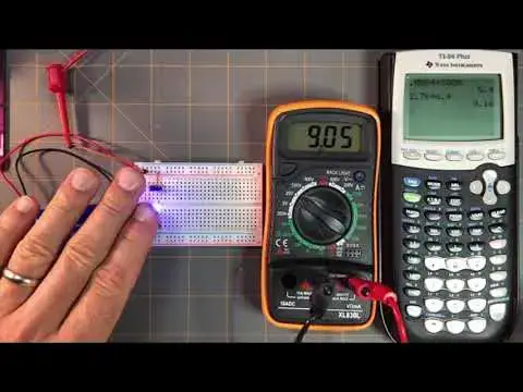
multimeter onto the orange jumper wire. I get 9.05 volts about that which is it's a
7:01
little off but it's very close. But it's pretty much on par
7:07
We're only off about one-tenth of a volt here, which is not a big deal
7:15
It's basically about the same. We're using a 9-volt battery. We get 9 volts
7:22
So we can see that how we check the current, we can use the current reading that we have
7:28
and then the resistance that we know in this circuit. We multiplied those two values together using only
7:35
law to get the voltage. And we measured the voltage drop across the blue LED, which
7:41
gave us a voltage drop of 2.76 volts. And recalling that a series circuit is a voltage
7:49
divider, we have a voltage division across the blue LED and a voltage division across
7:55
the resistor, since these are the only two components in this circuit. And we add those
8:03
two voltage drops in our circuit together and we should get the voltage supply
8:09
which is about 9 volts