0:00
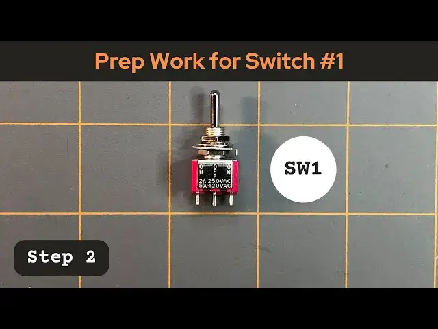
Okay, this is step two for switch one for the DIY 3220 point breadboard project
0:09
In step one, we took a red wire and we connected it to terminal two of the switch
0:20
For step two, we're going to do pretty much the same thing
0:24
We're going to take another web wire at about. We're going to cut a length about 12 inches
0:34
Again, it doesn't have to be exact. And then once I get this cut off, I'm going to strip one end of the wire at about an eighth of an inch or so back
0:52
and what I'm going to do is I'm going to twist that a little bit
1:01
So I have my wire end exposed. And we're going to solder this end to terminal number five for switch one
1:16
So again, referring to this schematic for the prototype of the power
1:22
supply for our DIY breadboard project. Terminal 5, if we follow this wire, in this case
1:32
it's a pink wire in the schematic, but we're using a red wire. It goes to this point in the
1:39
prototype schematic and it connects to this red wire here that goes to this red binding post for our power output And I have a red binding post here And what we eventually do is on the other end of this
2:00
wire that we just stripped is attach a ring connector on it
2:06
And it's a ring connector. This one's a small one, but it's just big enough to fit
2:13
on this little end post. post of this binding post and then there'll have be another little nut or that will
2:25
screw on here and keep it in place. So first we have our 12 inch strip of red wire. We've
2:35
already stripped the end of it. What I want to do is get my helping hands again
2:48
And again, we're going to be soldering this new wire to Terminal 5, which is right across from Terminal 2
3:05
So this is Terminal 5, as seen here. we're going to first ten the end of the stripped wire we just stripped
3:27
Just a little bit. And then I'm going to ten terminal number five
3:36
now I will attach our second wire to terminal 5
4:12
So the wires attached now. And again, just like before, we'll take a piece of heat shrink tubing
4:27
Again, we'll take a piece of heat shrink tubing. I'm gonna cut a little bit of this off, about half of it
4:37
I just need enough to cover the end or to cover where we solder it at on the terminal here
4:48
Again, that way we're protecting that terminal in the wire. We don't want it exposed just in case there's a short or something that could happen here if it's not protected
5:02
So we want to protect that area. So I'm going to slip it all the way down over that terminal and over that terminal
5:10
and over the wire. I'm going to turn this so maybe you can see it a little better
5:16
And then what we're going to do is take our heat gun. And I'm just going to heat it up to shrink that tubing
5:26
So now that part is done. done. So now we need to strip the other end of the wire that we connected to pin 5
5:52
Again, just strip about an eighth of an inch or so back, just enough to expose the wire
6:02
I'll give it a little twist. and we're going to connect our ring connector or our, yeah, the ring connector
6:14
And I'm going to slide it in there until the tip, the very end of it's just exposed
6:26
I don't know. Get the camera to focus on it. There we go
6:31
maybe not quite that much, but just outside. And then I'm going to take my crimper tool
6:45
And I'm going to crimper it. Just like that. And then I'll make a little tug on the ring connector to make sure it's nice and snug
7:11
And again, this ring connector will eventually go to a red binding post
7:18
And I got one that just fits over that end there. And then we'll put another nut on there to screw it down