live_tv
Livestream Starting Soon
00
Hours
:
00
Minutes
:
00
Seconds
Up next in 10

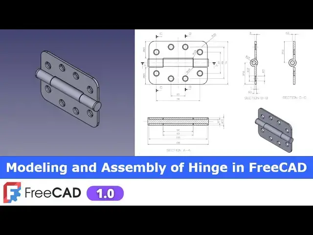
Modeling Assembly of Hinge in FreeCAD | FreeCAD Tutorial | FreeCAD Assembly | Mechnexus |
Dec 31, 2024
#freecad #freecadtutorial #freecadpartdesign
In this video I have explained How to Model Part in FreeCAD with the help of part design Workbench.
▶️ Visit my website for more info on FreeCAD-:
https://mechnexus.com/
▶️ Get my FreeCAD Crash Course for beginner-:
https://www.udemy.com/course/freecad-course-for-beginner/?referralCode=3BA9B526A12F96295D44
▶️ Download Source File of Tutorial-:
https://mechnexus.com/mechnexus-youtube-tutorial-source-file/
▶️ Become my Patron on-:
https://www.patreon.com/c/mechnexus/membership
▶️ Buy Me a Coffee
I am very grateful that you watch my videos and I am constantly trying to improve the quality of the videos on this channel. If you'd like to help me do this, please consider supporting me so that I can to continue to produce content for your enjoyment.
👉 Help support this channel by buying me a coffee: https://ko-fi.com/mechnexus
Show More Show Less View Video Transcript
0:00
Hello friends welcome to Free tutorial
0:02
and in this tutorial we will do modeling
0:05
and assembly of this H as you can see
0:08
that uh I have a model it and I have
0:12
assembled it and you can see that uh my
0:16
isometric view is matching with my
0:18
drawing isometric view so we will uh
0:22
create this assembly with the help of a
0:25
default assembly
0:27
workbench so this is is the very simple
0:30
tutorial to understand the assembly
0:34
workbench of a free care so I will close
0:37
this file and uh create a new
0:40
file you can also visit my website Mech
0:43
nexus.com where I write articles and
0:46
tutorials on freead you can download my
0:50
tutorial source file from here tutorial
0:53
source file page and you can also
0:56
support me by buying a cup of coffee on
1:01
kofi.com your uh small support will help
1:05
these channels to grow and it will
1:07
motivate me to create more awesome
1:09
content on fread I thanks to all my
1:13
supporter those who have supported me by
1:16
buying a cup of
1:18
coffee so keep supporting and uh it will
1:22
help me to grow this Channel and it will
1:26
motivate me to create more awesome and
1:29
useful full tutorials on freeat so let's
1:32
come back to our tutorial so first I
1:36
will create a new file and now I will uh
1:40
insert my body and I will on my origin
1:43
plane so now so if we zoom out so we can
1:49
see that uh these two hints are
1:52
assembled with the help of a pin and we
1:55
can see the details in the section view
1:58
now uh first thing which I will do is to
2:02
create this
2:04
body and we will save as this body and
2:07
we will make the body of other
2:10
sides so let's start our
2:13
tutorial so first I will select the
2:16
right
2:19
plane and click on the
2:22
sketch and I will off the origin
2:26
plane now on the right plane we will
2:29
switch to the side view and uh we can
2:32
find the details
2:35
here
2:37
so here is of diameter 13 and if you go
2:42
in a section view so here is a diameter
2:46
7 so I will create a circle
2:50
here and select smart Dimension and
2:54
provide it uh 13
2:58
mm and now
3:01
here I will create a
3:11
rectangle this will be the r
3:15
rectangle and now I will uh delete this
3:20
line and click on the
3:24
trim and trim
3:27
this this and this is and now we will
3:32
give the dimension so if we Zoom it we
3:35
can see the dimensions here so from
3:38
Center to this Edge is a
3:40
4.5 so I will select a
3:45
dimension and provide it
3:51
4.5 and I will move
3:54
it and here from Center to this age is
3:59
of 30
4:00
7.5 so I will select this and this and
4:05
provide it uh
4:08
37.5 and
4:10
here this is the 4.5 and the thickness
4:14
is of 3 mm so I will select it and uh
4:20
provide the 3 mm
4:22
now I will uh close
4:26
it and we will extrude it so to get
4:30
Extrusion
4:32
distance we will move to the section
4:34
view so Extrusion distance we can uh see
4:38
here is of 102 so I will select the
4:42
sketch click on
4:43
extrude and give the
4:47
102 and here I will uh keep it symmetric
4:51
to the plane and uh click on
4:53
okay
4:57
now we will uh remove the material on
5:01
this side but we will do at uh end
5:05
because I will save this part and uh
5:09
that will be helps to model the hinge of
5:13
the other side so here I will give these
5:16
two fillets so we will find out the
5:19
fillet details so it is a r10 fillet of
5:22
a typical type which means all four
5:25
corners having the r10
5:27
fets now I will select the fet tool and
5:32
uh select this
5:35
hede and uh this
5:40
hede and give the value
5:44
R1 and uh click on
5:50
okay now our uh next feature is to
5:54
create this counter s hole whose detail
5:58
is given here it is a Dia 8o through and
6:03
this diameter 10 and with depth of a 1
6:07
mm so I will switch to the front view
6:10
and uh select this pH and click on the
6:14
sketch and I rotate my
6:17
model and uh I will switch to the main
6:21
View and here are the four
6:23
holes so I will select a circle
6:27
tool create a tool circles and I will
6:31
provide the symmetricity
6:35
constraint and a distance is of
6:38
25 so I will select this and this and uh
6:43
provide the distance 25 and this is of 8
6:49
mm and select this and this and made it
6:54
equal click on the project geometry and
6:58
I will project it
7:00
so now if we move to the side view
7:05
so this is given the
7:08
55 so we will switch to the
7:14
wireframe wireframe
7:17
and here it is given a 55 which means
7:21
that
7:22
uh from the age it will be the 10
7:27
mm so select the smart dimension
7:32
iion 10
7:35
mm and
7:38
now here are the two
7:41
holes so I will uh
7:45
create the two
7:47
circles and uh make it
7:54
symmetric and now view the dimension of
7:57
76
8:00
select this and
8:02
this give the dimension
8:05
76 now we will constrain this ho so we
8:09
will select the dimension tool and
8:11
provide vertical dimensions and now here
8:14
we will uh link the
8:16
equations which is I will create a
8:20
bracket give it a
8:22
75 -
8:24
37 close the bracket divide by 2 so it
8:28
will calculate
8:30
distance and now I will close it so
8:33
here I will create a counter Sun hole so
8:37
select the whole tool and here is my
8:40
drill size of 8 mm and I will say it
8:43
through all and from here I will select
8:46
the counter sunk and the diameter is of
8:50
uh 10
8:53
mm with a depth of 1 mm
8:57
[Applause]
9:03
so click on okay
9:06
now we have created the hole now we will
9:10
create a cut so here Dimension is given
9:14
52 and 53 so this is the 52 and other
9:19
side is a 53 and there is a. 5.5 mm
9:23
clearance on the both the sides so I
9:25
will select this pH and click on the
9:28
sketch and I rotate my model and I will
9:33
switch to the wireframe
9:36
view
9:37
now I will simply create a rectangle and
9:42
I will project this Outer Edge click on
9:45
the project project it and uh select
9:49
this point and line and add a
9:53
coincidence and select the dimension
9:55
tool and uh provide it uh to
10:01
6 and I will also project this bottom
10:05
ede because position is given
10:09
29.5 click
10:12
it and select
10:15
Dimension and provide it
10:20
29.5 and set the vertical Dimension
10:23
rough set it 30 click on
10:27
close and now
10:32
will switch to the flat
10:34
lines so here I will remove the material
10:38
completely so select this page click on
10:40
the
10:41
cut say it through all and symmetric to
10:45
the plane click on okay and now select
10:49
this cut and uh mirror it on the other
10:53
side so click on the mirror tool and
10:56
from here I will select my reference
10:59
select this mid plane and click on okay
11:03
and now here is a drill of 7 mm so I
11:07
will select the phase and uh click on
11:09
the
11:10
sketch and uh create a
11:13
circle select
11:16
Dimension give the value 7 mm click on
11:20
close and uh click on the whole
11:24
tool give the 7 mm and say it through
11:28
all
11:29
say okay now if you see our drawing
11:33
there is a fillet of
11:35
r1.5 so select the fillet tool
11:41
and select this
11:44
age and uh this age and give it uh
11:51
1.5 and click on
11:54
okay so this is how we have a
12:00
made this bottom hinge let's save it and
12:05
I will uh save it uh as
12:09
R1 click on Save and now to save our
12:14
time we will save this part and we will
12:18
create the other hinge because the whole
12:21
positioning in the same and size is also
12:25
same all we have to modify this cut so I
12:29
will go to the file and click on the
12:31
save as and I will give it a part 0
12:37
to
12:42
R1 now I will uh close it and open my
12:46
fresh
12:50
part so here is my part
12:53
two now here I will delete this fillet
13:01
and delete this mirror and
13:08
cut and here we have the sketch and uh
13:12
we will edit this
13:15
sketch and uh remove this 26
13:19
dimensions
13:21
and or better to delete this sketch as
13:25
well and create a fresh sketch for the
13:29
cut so select the ph and uh click on the
13:33
sketch and now rotate my
13:36
model and uh I will create a rectangle
13:41
and uh here we will switch to the
13:46
wireframe and
13:48
now here is a dimension 53 so first I
13:53
will make this and this symmetric with
13:56
my
13:57
Axis and I will give the dimension uh
14:02
53 and
14:04
now here is a dimension is a
14:08
29.5 so I will select it and project
14:14
this age so that I can give the
14:18
dimension now select this
14:22
and and give the
14:25
29.5 and this vertical I will give the
14:29
Dimension because I wanted to remove the
14:32
material now I will switch to the flat
14:36
lines and here I will completely remove
14:39
the material select the cut and from
14:43
here say it through all and set it
14:45
symmetric to the plane and click on okay
14:53
now we will uh check the features so we
14:56
have fillet we have holes we have this
14:59
these holes so we will uh change the end
15:02
condition of this
15:05
hole so it
15:07
is failing so we will
15:11
uh delete it because it is not going
15:14
through all if I see the whole or uh
15:22
simply through all it is not detecting
15:24
here so why not delete the
15:29
this
15:38
hole and here I will on this pocket so
15:43
it was created on this phas so best
15:46
thing which we can do is to redefine the
15:50
sketch plane so we will go to our sketch
15:54
and uh go to the our uh attachment
15:57
editor
16:00
and here we will on our
16:04
body and here the attachment editor I
16:07
will delete it and select this face
16:10
again and click on
16:14
okay and let's on our whole
16:18
sketch
16:20
and edit the whole
16:29
let's select the
16:34
reverse and let's
16:37
give uh total is uh let's give the
16:42
120
16:44
okay now I will on this pocket and let's
16:49
see what
16:51
happened so here we have to
17:00
it is better
17:07
to so we have created the sketch and now
17:11
we will uh create a hole so we will uh
17:13
select the phase and click on the
17:16
sketch rotate our
17:19
model
17:23
and select the
17:25
circle and select the diameter
17:29
give it 7 mm click on close select the
17:33
whole
17:35
visard and this is of 7
17:39
mm and make it through
17:42
all click on okay
17:47
now here is a fillet of r1.5 so I will
17:51
select
17:52
this and uh this and click on the fillet
17:57
and give it to one
18:00
.5 click on
18:03
okay so we have created both the hinge
18:06
and
18:08
now we will uh create this pin so I will
18:13
create a new file create a body and on
18:16
my origin plane and here creation of
18:19
this pin is very simple if we Zoom to
18:23
this uh section view so we will simply
18:26
select the front plane and click on the
18:28
SC sketch go to the model Tab and hide
18:32
the origin so here I will uh simply
18:35
create a rectangle and now I will select
18:39
the
18:40
polyline select this vertical horizontal
18:44
and
18:44
vertical and
18:46
here I will make it vertical and this
18:50
one
18:51
uh
18:53
vertical and we do not require this line
18:56
so we will uh simply
18:59
trimit and now we will make this pin
19:03
symmetric to this axis so I will uh
19:07
click on the symmetricity constraints
19:09
like this point this point and this
19:11
axis
19:13
similarly this point this point and this
19:18
axis so select the horizontal Dimension
19:21
provide the
19:23
106 and uh this one is of 102
19:31
102 and uh this is the diameter 7 so
19:35
from this point to this point it will be
19:40
3.5 and select this to this which is of
19:45
13 / 2 so 6.5 is radius now I will move
19:51
this
19:52
Dimension and here I will provide the
19:56
horizontal constraint
20:08
so here it is
20:12
uh not updating okay now it become
20:16
horizontal now I will uh close it and
20:21
create a simple Revol and I will select
20:24
my reference this uh xais click on okay
20:29
now I will uh save my pin as a part
20:33
three so part 03 I have already modeled
20:37
it so I will give the revision
20:41
R1 so we have created all three parts
20:44
now we will create a assembly so here I
20:48
will create a new file and from here I
20:52
will switch to the assembly
20:54
workbench and create an
20:57
assembly and this is active you can
21:00
check it active object and now I will
21:03
insert my body click on open file so
21:07
here the first I will insert it my part
21:11
one say insert and now select the
21:16
body so first save your file so let's
21:20
save it so hinge assembly I will uh VI
21:23
it
21:25
R1 and uh I will say yes
21:29
click on okay now I will again insert
21:32
the same
21:34
body uh it is a same but cut is
21:36
different which is having the different
21:38
name so I will insert
21:42
the part two or 2
21:46
R1 and select
21:48
it and click on okay
21:52
now
21:54
here I can give my
21:57
name let's uh press f2 and give it a
22:01
hinge
22:05
bottom and this one is of a Hing
22:10
stop and now select the second one and
22:14
uh click on the
22:18
transform and uh we will rotate it
22:24
so this will be like this as for our
22:29
drawing now click on okay we will uh set
22:33
the hinge position if you see in the
22:35
Right
22:36
View so we have to make this face of my
22:41
top hinge and bottom hinge should be
22:43
parallel so I will select this face and
22:47
this pH and give the distance
22:51
constraint and here I have provided
22:55
distance zero and click on okay and
23:00
now I will select my top
23:07
hinge and go to the transform tool and
23:10
uh move
23:15
it okay
23:18
now I will select uh assembly and
23:22
activate it and select
23:25
this inner diameter and uh this inner
23:32
diameter and add the cylindrical
23:36
joints click on okay and now here you
23:41
can see that this and this are the
23:43
parallel and
23:45
now I
23:47
will move my top
23:51
hinge and provide the5 mm
23:56
clearance so I will select uh this
24:00
phas and this
24:04
phas and
24:06
uh first activate
24:10
it so this pH will match with this pH
24:14
with5 mm clearance so here is a distance
24:19
joint and here I will give the
24:23
0.5 I click on okay so now if you see
24:28
the right Right
24:29
View so this and this face are the
24:35
parallel so this is how we have a model
24:39
and assemble the hinge and
24:42
now we will insert the pin so we will go
24:45
to the object and uh select this pin and
24:51
click on okay so you can see that uh pin
24:54
has been placed as exact locations I can
24:58
provide the constraint okay to the my
25:02
pin or I can simply place it at a ground
25:07
so instead of providing the constraint
25:10
it is uh fit at correct locations so I
25:14
will make it ground else I can provide
25:16
the constraint
25:18
so this is how we have a model and
25:23
assemble the hinge in a free cat and uh
25:27
we have also learn the modeling with use
25:30
of assembly default workbench so this is
25:34
all about this tutorial thank you for
25:36
watching and thank you for your valuable
25:57
time for
#CAD & CAM