live_tv
Livestream Starting Soon
00
Hours
:
00
Minutes
:
00
Seconds
Up next in 10

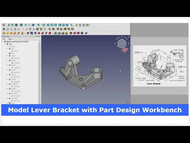
Model Lever Bracket with FreeCAD Part Design Workbench | FreeCAD Tutorial | Mechnexus |
May 16, 2025
#freecad #freecadtutorial #learnFreeAD
In this video I have explained How to Model Lever Bracket with FreeCAD Part Design Workbench.
▶️ Get my Complete FreeCAD Course : From Zero to Expert !
https://ko-fi.com/s/1ab4385434
▶️ Join my channel membership and keep supporting my work:
https://www.youtube.com/channel/UCcn6z2whMaFu-_LDsEXCfVA/join
▶️ Visit my website for more info on FreeCAD-:
https://mechnexus.com/
▶️ Download Source File of Tutorial-:
https://mechnexus.com/mechnexus-youtube-tutorial-source-file/
▶️ Buy Me a Coffee
I am very grateful that you watch my videos and I am constantly trying to improve the quality of the videos on this channel. If you'd like to help me do this, please consider supporting me so that I can to continue to produce content for your enjoyment.
👉 Help support this channel by buying me a coffee: https://ko-fi.com/mechnexus
Show More Show Less View Video Transcript
0:00
hello friends welcome to FRECAT tutorial
0:02
and in this tutorial we will model this
0:04
lever bracket in frecat as you can see
0:07
that uh I have already modeled it and I
0:09
will show you from the scratch how you
0:10
can model it i will close this file and
0:14
create a new file if you want to learn
0:17
free CAD from the scratch then you can
0:19
buy my complete free course from zero to
0:23
expert this course also available on
0:26
Udemy but uh problem is that uh UDMI
0:30
only give me the
0:32
37% of a core selling you can see here
0:35
user had paid $15 but I have only got $5
0:42
if you wanted to see the review of my
0:45
course you can go to the Udemy and
0:48
search for the free CAD and you will see
0:51
my course complete free CAD course from
0:54
zero to expert and this course is took
0:57
by the more than 2,000 students and I
1:00
have got the rating of
1:03
4.1 for the demo lectures you can expand
1:07
it and uh see the demo lectures and the
1:11
course structure but I will request you
1:15
if you found my course interesting and
1:19
uh reviews of the other student on Udemy
1:23
then I would request you to buy my
1:27
course from the my coffee shops because
1:31
if you buy from here it will help me a
1:34
lot so once you buy my course you will
1:38
be redirected to the Google drive and
1:41
here is the my course complete free
1:44
course from zero to expert go inside and
1:49
uh the sections I have shown you on my
1:53
Kofi shop page so exactly same lectures
1:58
under the section is created for example
2:03
section one is a introductions to
2:05
freecad 1.0 and what is new in a freead
2:08
1.0 so if you go to the section one so
2:12
there are the 18 lectures and if you go
2:16
inside of the sections one you will find
2:19
the 18 lecture total and once you go to
2:22
the lecture one you will find a video
2:25
file which you can download to your
2:28
system and you can watch it and this
2:33
course is updated on a equal interval of
2:36
a time once the new feature receives
2:38
came and uh once you purchase the course
2:42
you have the lifetime access to the
2:45
course and in the case of any doubt any
2:48
query you can mail me at
2:52
adminxus.com you can find my course link
2:56
on my YouTube channel you can see the
2:58
course link and uh you can also find my
3:02
Kofi course page link on uh pin comments
3:06
and uh video
3:08
descriptions so here I have created a
3:11
new file and first thing which I will do
3:13
is to insert my body and on my origin
3:16
plane and I will select this top plane
3:20
to create our base profile we will
3:22
create this uh base on the top plane so
3:26
click on the sketch now go to the model
3:29
tab and uh hide
3:31
it
3:35
now here we will uh create three
3:38
construction
3:40
circle and
3:43
uh we will give the dimension so first
3:46
construction circle we will create here
3:48
and select it and make it
3:50
construction and I will select this and
3:54
uh add uh
3:56
tangency select
3:58
this and add a
4:01
tangency second construction circle will
4:03
be this
4:05
one so select a circle and uh make it uh
4:13
tangent and uh we will select a
4:15
threepoint arc and uh create one arc
4:20
here and uh we will again select a
4:23
circle and create one circle here which
4:26
is for
4:28
this now we will give the dimensions
4:34
so we will select horizontal dimension
4:36
select this and uh this and add the
4:39
dimension of
4:44
241 let's uh arc
4:48
smaller and from here to here it is of
4:57
106 select horizontal dimension select
5:00
this and this and add 70 mm
5:04
and let's uh move this
5:08
dimension and uh give it a diameter of
5:14
38 and select this and this and made it
5:18
equal select this circle made it
5:21
construction and give it a diameter of
5:27
28
5:30
and from this center to this center
5:35
vertical dimension is of
5:38
38 and I will move
5:41
it and this
5:45
radius or we give you the diameter of
5:49
38 and
5:52
now we will select a line
5:55
tool create a line
6:00
and join this line with this
6:03
arc and uh go to the conflict constraint
6:06
and deactivate
6:09
it and we will uh move
6:13
it here and add this and this tangent
6:18
relation
6:25
now we will create a vertical
6:28
line select line
6:31
tool create a vertical line and uh
6:34
select a threepoint
6:38
arc and uh go to the conflict and
6:42
deactivate it select this and this and
6:46
add a tangency
6:49
select
6:50
diameter and add it uh
6:55
76 and uh select the line
6:58
tool draw the horizontal line select
7:01
this and this and add a
7:04
tangent and uh select the threepoint arc
7:08
select this and this
7:11
and select this and this and add a
7:14
tangent select this and this and add a
7:17
tangent
7:20
now we will uh select this arc and uh
7:24
provide the radial dimension of
7:29
89 and uh select this and this and add a
7:33
horizontal
7:37
relation and uh select this point and
7:40
this
7:41
point let's add a
7:44
vertical no this we will delete it and
7:52
here we will
7:54
uh add a tangency here select uh this
7:58
and this and add a
8:02
tangency and select this and made it
8:07
construction and
8:09
now select uh this center point and this
8:13
center points and add a horizontal
8:15
relation so our uh sketch is fully
8:19
constrained we will uh come out of
8:23
it and we will extrude it to the
8:26
distance of 19 mm extrude it to the 19
8:30
mm click on
8:34
okay now we will add R19 fillet here and
8:40
here so we will select these two edges
8:44
and click on the fillet and add here
8:47
value
8:48
R19 click on
8:55
okay now we will create this boss so for
9:00
this we will select the face and click
9:01
on the
9:02
sketch click on the project
9:05
geometry select the circle
9:09
create a circle equal
9:12
to and uh select the sketch click on
9:16
extrude and add it uh 45 mm click on
9:20
okay and here we are seeing the two
9:23
different solids so we will uh select
9:26
the
9:29
pad
9:30
and we will refine the shape set uh
9:34
refine is
9:37
true now we will create this
9:42
plate on uh this face so we will select
9:46
the face and uh click on the sketch now
9:50
switch to the isometric and
9:53
here I will project this
9:57
edge
9:58
and I will uh create uh a
10:06
line and
10:08
uh we will switch to the front view and
10:13
from here we will uh switch to the
10:16
wireframe and Here we will uh create
10:20
this circles and before that we will
10:24
project this uh
10:25
geometry so click on the project and
10:28
project it
10:32
and create a
10:34
circle which is of
10:37
uh diameter 70
10:42
select
10:43
uh
10:45
diameter and uh provide here value 70
10:49
mm and we will insert one midpoint here
10:55
because we wanted to get
10:58
axis so we will uh click on the point
11:02
and create a point and this is of uh 76
11:07
so this will be at the center which will
11:11
be
11:14
38 and now from this point to this point
11:18
horizontal dimension we will add a
11:21
146
11:23
and from this point to this point
11:28
vertical dimension of uh
11:33
41 let's uh move the
11:37
dimensions and
11:39
now we will uh create a angular
11:47
line and we will define the
11:51
angle select this and this and define
11:54
the angle of uh
11:57
77 select the angle and define it uh 77
12:07
and
12:09
now we will uh constrain it so we will
12:15
select this and this and add a tangent
12:18
select this and this and add a tangent
12:21
so here is a
12:27
conflict because here this line is
12:31
coincidence which we do not want
12:34
to and we will uh made it construction
12:40
and from here we will create a line and
12:45
we will uh create uh one fresh
12:48
line to join this point and here we will
12:54
uh remove the conflict and here we will
12:58
uh add a angular dimension of 77 and
13:03
then we will select this uh circle and
13:05
this line and uh add a
13:09
tangency and here we will use the trim
13:12
tool to trim the
13:15
geometry so here is our uh sketch is
13:19
fully constrained we will close
13:22
it press zero for isometric and v7 for
13:26
the shaded
13:27
view and uh we will select the sketch
13:30
click on extrude and from here we will
13:33
select the reverse and provide a value
13:36
of uh 19 mm click on
13:40
okay now uh we will create this circular
13:43
profile so for this we will uh select
13:46
this back face and click on the sketch
13:49
now we will uh switch to the isometric
13:52
and we will click on project geometry
13:54
and project this switch to the front
13:57
plane and
13:59
uh create a circle and again create a
14:03
circle and internal one provide uh
14:09
445 click on
14:12
okay and now we will select the sketch
14:15
click on extrude and here in options we
14:19
will select two dimensions dimension one
14:23
will be 22 and uh dimension two will be
14:35
38 let's reverse the
14:40
value yes so this is how it will be look
14:47
like because I have not tick mark here
14:50
reverse click on okay so you can see
14:53
that uh this boss is matching with our
14:56
model and
14:58
now we will create this uh triangular
15:01
rib so first we will select the face and
15:05
click on the sketch and we will click on
15:08
the project geometry
15:11
click on the bottom project
15:15
geometry and we will uh switch to the
15:20
wireframe from here uh go to the
15:23
wireframe and uh here we will create a
15:27
rectangle and select this point and this
15:31
line and add a coincidence and we will
15:34
delete this line and uh then we use trim
15:39
tool to trim this and select threepoint
15:43
arc to create an equal
15:46
arc and now we will uh select this
15:49
horizontal line and uh provide the
15:52
dimension of uh 13 mm and here is a
15:56
conflict say delete or
16:00
deactivate
16:03
now we will move it select uh this point
16:07
and this point and horizontal dimension
16:10
13 /
16:12
2 and we will move it select this arc
16:17
and this and made it equal so we have a
16:22
fully constrained profile we will uh
16:24
close it press V7 for the shaded view
16:28
and uh we will create a rib of 41 mm so
16:32
select the sketch click on extrude
16:35
and add it 41
16:38
mm click on
16:41
okay and
16:44
uh now we will remove the material so we
16:47
will select the face and click on the
16:50
sketch click on project geometry project
16:54
this edges and switch to the
16:57
wireframe and select the line
17:01
tool and
17:06
and create a triangular profile click on
17:09
close press V7 for the shaded view and
17:12
click on extrude cut and from here
17:15
select up to face and select this back
17:18
face
17:22
now there is a one rib on the other side
17:25
which we can see here in a bottom view
17:29
projection
17:31
so we will select this face and click on
17:35
the sketch and from here we will switch
17:38
to the wireframe and we will click on
17:41
the project geometry and project
17:43
this two vertical edges and it is the
17:48
projection of these two edges
17:52
now select the line
17:55
tool create a equal
18:00
line and uh click on the project
18:02
geometry and project this outer diameter
18:06
select
18:07
uh threepoint
18:10
arc and select this and
18:13
this and click on close
18:17
and press V7 for shaded view
18:21
and
18:23
here we will click on extrude and from
18:27
here we will select uh up to face and
18:30
select this
18:31
face click on okay
18:36
now we will select the face and uh click
18:41
on the
18:43
sketch and click on project geometry
18:46
project uh edges and we will switch to
18:51
the right view and switch to the
18:54
wireframe so that we can clearly see the
18:56
points and we will uh close the
19:02
profile and create a
19:06
cut now click on
19:09
close now press uh V7 for shaded view
19:13
and we will create a cut select it and
19:16
create extrude cut and from here select
19:20
up to face and select this face click on
19:25
okay press
19:28
zero and
19:31
now we will uh move to the next feature
19:35
which is to create this
19:38
rip so for this we will uh select the
19:42
face and uh click on the sketch switch
19:45
to the isometric and click on project
19:48
geometry and project this outer diameter
19:51
and
19:53
here I will select a rectangle tool and
19:57
uh create a rectangle and I will select
20:00
this line and delete it and go to the
20:04
trim select it and uh trim it and here I
20:09
will uh select a threepoint arc and
20:13
create an equal arc as per projection
20:17
and now we will uh give the dimensions
20:20
so first I will select this and provide
20:22
the horizontal dimension of 13
20:25
mm and I will
20:28
uh move it and select this point and
20:33
this point and provide the horizontal
20:37
dimension 13 /
20:40
2 and I will move it
20:46
so this is vertical
20:49
dimension so this is
20:52
coming
20:53
85
20:56
yes now we will uh select
21:05
uh this arc and this and made it
21:09
equal so our uh profile is uh fully
21:13
constrained
21:14
i move the dimensions so that you can
21:16
clearly see it so this is the 13 6.5 and
21:21
85 click on close and click on extrude
21:26
click on
21:27
reverse select up to phase and select
21:30
this bottom face and click on
21:34
okay
21:35
now we will uh create a cut and it is a
21:40
38 from the this face so we will select
21:44
the face and click on the sketch and uh
21:48
click on project geometry and project
21:50
this edges and
21:53
now switch to the
21:56
wireframe select line tool
21:59
and create a triangular
22:07
profile click on close
22:10
press V7 for shaded view
22:12
and here it is not uh perfectly
22:17
triangular we will edit it and here it
22:20
is 38 so we will delete this line and
22:25
click on this edge and project it and
22:33
uh and we will close the profile and
22:36
here it is given the distance 38 so we
22:41
will select this point and this point
22:43
and add the dimension of
22:47
uh
22:49
38 and let's see what is unconstrain so
22:54
we will select this and this and add a
23:02
coincidence select this point and this
23:04
and add a coincidence
23:09
and
23:10
here we will select this and this and
23:12
add a merge so here we will uh delete it
23:17
so this is the
23:19
profile and uh we will come out of it
23:22
and create a cut select extrude cut and
23:26
from here select up to
23:28
face and select this face and click on
23:33
okay
23:36
now we will press zero for isometric and
23:39
we will create a cut so we will select
23:42
this top face and uh click on the
23:46
sketch click on project geometry so we
23:49
can get a center here select a circle
23:53
and this is the diameter of
23:58
50.8 and click on close and click on cut
24:04
and from here I will say a through
24:10
wall now uh we will create this uh
24:14
counterboard holes four counterboard
24:16
holes so we will select the face and
24:19
click on the sketch and here we will
24:22
project the
24:23
geometry click on project geometry
24:26
project this
24:27
arc project this arc and project this
24:31
arc and uh this is the drill of 14 mm so
24:36
we will create a three circle here and
24:39
one circle
24:41
here so let's click on the circle and
24:45
create a four circle 1
24:49
2 3 and 1 4 and this will have the
24:55
horizontal relation with this so we will
24:57
select this center points and add a
25:00
horizontal relation and now I will
25:03
select horizontal dimension and add a
25:06
horizontal dimension of
25:09
178 and now I will uh constrain one of
25:13
the circle which is of a diameter 14 and
25:17
press control key and I will select all
25:20
the
25:21
circles and uh made it
25:24
equal now close it and now here we will
25:28
uh create a counterboard holes so select
25:31
the sketch and we will use the whole
25:33
wizard tool and
25:35
here we will select counter board
25:38
through release of 14 mm and this
25:42
diameter of uh 28 with a depth of 2
25:49
mm click on
25:53
okay
25:55
now here if you see here here is a
25:58
material is cutting so we will select
26:02
the phase and click on the sketch and we
26:05
will click on the project geometry and
26:08
project this and uh we will select a
26:11
threepoint
26:13
arc and create an arc select this and
26:17
this and add a tangent and we will close
26:21
this
26:24
profile and uh let's uh deactivate it
26:28
click on close and click on
26:31
extrude click on
26:34
reverse select up to face and we will
26:37
select this face click on okay now we
26:40
will select the last
26:42
feature and uh set
26:45
refine is
26:48
true so you can see that uh this
26:51
perfectly got merged press zero so this
26:55
is how we have modeled this uh lever
26:58
bracket in a
27:00
freecad this is all about this tutorial
27:03
how to model lever bracket with the help
27:05
of part design workbench thank you for
27:08
watching and thank you for your valuable
27:22
time heat heat
28:06
heat
28:10
heat
28:12
heat heat
#CAD & CAM