Up next in 10

FreeCAD Part Modeling Tutorial | FreeCAD Tutorial | 3D Modeling | Learn FreeCAD | Mechnexus |
Sep 20, 2025
#freecad #freecadtutorial #learnFreeAD
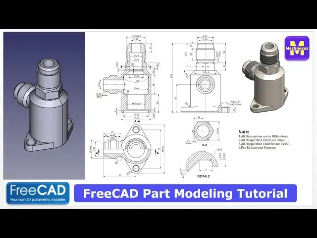
In this video I have explained How to Model Part in FreeCAD with the help of part design Workbench.
▶️ Get my Complete FreeCAD Course : From Zero to Expert !
https://ko-fi.com/s/1ab4385434
▶️ Join my channel membership and keep supporting my work:
https://www.youtube.com/channel/UCcn6z2whMaFu-_LDsEXCfVA/join
▶️ Visit my website for more info on FreeCAD-:
https://mechnexus.com/
▶️ Download Source File of Tutorial-:
https://mechnexus.com/mechnexus-youtube-tutorial-source-file/
▶️ Buy Me a Coffee
I am very grateful that you watch my videos and I am constantly trying to improve the quality of the videos on this channel. If you'd like to help me do this, please consider supporting me so that I can to continue to produce content for your enjoyment.
👉 Help support this channel by buying me a coffee: https://ko-fi.com/mechnexus
Show More Show Less View Video Transcript
0:00
Hello friends, welcome to free tutorial
0:02
Hello friends, welcome to free tutorial
0:02
Hello friends, welcome to free tutorial and in this tutorial we will model this
0:05
and in this tutorial we will model this
0:05
and in this tutorial we will model this uh pipe fitting in a free. As you can
0:08
uh pipe fitting in a free. As you can
0:08
uh pipe fitting in a free. As you can see that uh I have already model it and
0:10
see that uh I have already model it and
0:10
see that uh I have already model it and I will show you from the scratch how you
0:12
I will show you from the scratch how you
0:12
I will show you from the scratch how you can model this part.
0:15
can model this part.
0:15
can model this part. So for this tutorial I am using the free
0:19
So for this tutorial I am using the free
0:19
So for this tutorial I am using the free version 1.0. So you must have at least
0:21
version 1.0. So you must have at least
0:21
version 1.0. So you must have at least 1.0 or higher version than this. So I
0:25
1.0 or higher version than this. So I
0:25
1.0 or higher version than this. So I will close this file and create a new
0:28
will close this file and create a new
0:28
will close this file and create a new file. You can also visit my website
0:30
file. You can also visit my website
0:30
file. You can also visit my website macexus.com
0:32
macexus.com
0:32
macexus.com where I write articles and tutorials on
0:35
where I write articles and tutorials on
0:35
where I write articles and tutorials on a free catad and you can read articles
0:40
a free catad and you can read articles
0:40
a free catad and you can read articles and tutorials in your language. Here I
0:43
and tutorials in your language. Here I
0:43
and tutorials in your language. Here I have provided the vast variety of
0:45
have provided the vast variety of
0:46
have provided the vast variety of language where you have to select the
0:48
language where you have to select the
0:48
language where you have to select the language and uh articles and tutorials
0:52
language and uh articles and tutorials
0:52
language and uh articles and tutorials will be get translated. Like here I have
0:55
will be get translated. Like here I have
0:55
will be get translated. Like here I have selected the French and you can see that
0:57
selected the French and you can see that
0:58
selected the French and you can see that it got translated in a French.
1:01
it got translated in a French.
1:02
it got translated in a French. You can also follow the stepbystep
1:04
You can also follow the stepbystep
1:04
You can also follow the stepbystep tutorials guide on my website. For
1:06
tutorials guide on my website. For
1:06
tutorials guide on my website. For example, here is a part modeling
1:08
example, here is a part modeling
1:08
example, here is a part modeling tutorial 145. And if you go on this
1:13
tutorial 145. And if you go on this
1:13
tutorial 145. And if you go on this tutorial, so here I have inserted the 2D
1:16
tutorial, so here I have inserted the 2D
1:16
tutorial, so here I have inserted the 2D drawings and I have uh inserted the
1:20
drawings and I have uh inserted the
1:20
drawings and I have uh inserted the respective stepbystep images with
1:23
respective stepbystep images with
1:23
respective stepbystep images with instructions to model the part.
1:27
instructions to model the part.
1:27
instructions to model the part. You can also access my mechanical 3D
1:31
You can also access my mechanical 3D
1:31
You can also access my mechanical 3D part library
1:33
part library
1:33
part library where I have inserted so many mechanical
1:36
where I have inserted so many mechanical
1:36
where I have inserted so many mechanical model.
1:38
model.
1:38
model. To access this part all you have to
1:41
To access this part all you have to
1:41
To access this part all you have to click on the image then you will be get
1:44
click on the image then you will be get
1:44
click on the image then you will be get directed to the Google drive where you
1:47
directed to the Google drive where you
1:47
directed to the Google drive where you will get the free get part as well as
1:49
will get the free get part as well as
1:49
will get the free get part as well as its 2D drawing.
1:52
its 2D drawing.
1:52
its 2D drawing. You can download this parts and modify
1:55
You can download this parts and modify
1:55
You can download this parts and modify it and use it in your projects. There is
1:59
it and use it in your projects. There is
1:59
it and use it in your projects. There is no any need to give the credits.
2:02
no any need to give the credits.
2:02
no any need to give the credits. This gallery is heavy so it might take
2:05
This gallery is heavy so it might take
2:05
This gallery is heavy so it might take five to 10 second time to load it. You
2:09
five to 10 second time to load it. You
2:10
five to 10 second time to load it. You can also access my 2D drawing library
2:13
can also access my 2D drawing library
2:13
can also access my 2D drawing library where I have uploaded so many mechanical
2:17
where I have uploaded so many mechanical
2:17
where I have uploaded so many mechanical 2D drawing in the form of a PDF. You can
2:22
2D drawing in the form of a PDF. You can
2:22
2D drawing in the form of a PDF. You can click on the image then you will get the
2:24
click on the image then you will get the
2:24
click on the image then you will get the PDF version of a drawing.
2:27
PDF version of a drawing.
2:27
PDF version of a drawing. You can download this drawing and uh you
2:30
You can download this drawing and uh you
2:30
You can download this drawing and uh you can create 3D model
2:33
can create 3D model
2:33
can create 3D model with respect to the dimensions shown and
2:36
with respect to the dimensions shown and
2:36
with respect to the dimensions shown and uh you can also see that uh how I
2:39
uh you can also see that uh how I
2:39
uh you can also see that uh how I provided the technical details.
2:43
provided the technical details.
2:43
provided the technical details. If you like my method of teaching and my
2:46
If you like my method of teaching and my
2:46
If you like my method of teaching and my contributions toward the 3D part library
2:49
contributions toward the 3D part library
2:49
contributions toward the 3D part library of a free CAD, you can support me on
2:51
of a free CAD, you can support me on
2:51
of a free CAD, you can support me on coffi.com.
2:53
coffi.com.
2:53
coffi.com. You can buy me a cup of coffee. Your
2:56
You can buy me a cup of coffee. Your
2:56
You can buy me a cup of coffee. Your small support will help this channels to
2:58
small support will help this channels to
2:58
small support will help this channels to grow and it will motivate me to create
3:01
grow and it will motivate me to create
3:01
grow and it will motivate me to create more awesome content on a free CAD. You
3:05
more awesome content on a free CAD. You
3:05
more awesome content on a free CAD. You can find my coffee donation link in a
3:09
can find my coffee donation link in a
3:09
can find my coffee donation link in a video descriptions and uh you can also
3:13
video descriptions and uh you can also
3:13
video descriptions and uh you can also see my Kofi page URL on my website here.
3:18
see my Kofi page URL on my website here.
3:18
see my Kofi page URL on my website here. So let's come back to our tutorial.
3:24
Here I have created a new file and I
3:26
Here I have created a new file and I
3:26
Here I have created a new file and I will create a body and then on the
3:30
will create a body and then on the
3:30
will create a body and then on the origin plane and uh we will first create
3:35
origin plane and uh we will first create
3:35
origin plane and uh we will first create this uh half portion and then we will
3:38
this uh half portion and then we will
3:38
this uh half portion and then we will revolve it. So for this as per the
3:42
revolve it. So for this as per the
3:42
revolve it. So for this as per the orientation we will uh select this front
3:44
orientation we will uh select this front
3:44
orientation we will uh select this front plane and click on the sketch. Go to the
3:48
plane and click on the sketch. Go to the
3:48
plane and click on the sketch. Go to the model tab and hide it.
3:51
model tab and hide it.
3:51
model tab and hide it. Now here I will select a rectangle tool
3:55
Now here I will select a rectangle tool
3:55
Now here I will select a rectangle tool and uh create a rectangle
3:58
and uh create a rectangle
3:58
and uh create a rectangle and uh I will define the total height of
4:02
and uh I will define the total height of
4:02
and uh I will define the total height of uh 135
4:07
and
4:09
and
4:09
and I will uh make everything as a
4:13
I will uh make everything as a
4:13
I will uh make everything as a construction
4:15
construction
4:15
construction and select the smart dimension and uh
4:17
and select the smart dimension and uh
4:18
and select the smart dimension and uh provide it uh 29 nine.
4:22
provide it uh 29 nine.
4:22
provide it uh 29 nine. Now
4:24
Now
4:24
Now select the line tool.
4:27
select the line tool.
4:27
select the line tool. Create a vertical line
4:30
Create a vertical line
4:30
Create a vertical line and
4:33
and
4:33
and create a rough profile and u
4:39
let's give the dimension. Select a smart
4:41
let's give the dimension. Select a smart
4:41
let's give the dimension. Select a smart dimension and give this a
4:45
dimension and give this a
4:45
dimension and give this a 74.
4:48
And uh this one is of uh
4:53
And uh this one is of uh
4:53
And uh this one is of uh 20.8.
4:56
And uh from the top to this give it uh
5:02
And uh from the top to this give it uh
5:02
And uh from the top to this give it uh 53.
5:08
So our uh sketch is fully constrained.
5:11
So our uh sketch is fully constrained.
5:11
So our uh sketch is fully constrained. We will close it. And from here we will
5:14
We will close it. And from here we will
5:14
We will close it. And from here we will use the revolve tool and say okay.
5:18
use the revolve tool and say okay.
5:18
use the revolve tool and say okay. So we have uh created the first base
5:20
So we have uh created the first base
5:20
So we have uh created the first base features. Now click on the save. And
5:23
features. Now click on the save. And
5:23
features. Now click on the save. And here I will uh give it a revision
5:28
here I will uh give it a revision
5:28
here I will uh give it a revision R1.
5:30
R1.
5:30
R1. And now
5:32
And now
5:32
And now we will create the next feature. So if
5:35
we will create the next feature. So if
5:35
we will create the next feature. So if we see the
5:38
we see the
5:38
we see the isometric model. So here we can see that
5:41
isometric model. So here we can see that
5:41
isometric model. So here we can see that there is a hexagon.
5:46
To create this hexagon, we will select
5:48
To create this hexagon, we will select
5:48
To create this hexagon, we will select the top face and click on the sketch.
5:51
the top face and click on the sketch.
5:51
the top face and click on the sketch. And now
5:53
And now
5:53
And now we will uh set our model to the right
5:57
we will uh set our model to the right
5:57
we will uh set our model to the right orientation. So let's switch to the
5:58
orientation. So let's switch to the
5:58
orientation. So let's switch to the isometric and then click on the top.
6:02
isometric and then click on the top.
6:02
isometric and then click on the top. Select the hexagon
6:06
and we will uh project this uh outer
6:10
and we will uh project this uh outer
6:10
and we will uh project this uh outer diameter.
6:11
diameter.
6:11
diameter. Select this point and this one and add a
6:14
Select this point and this one and add a
6:14
Select this point and this one and add a coincidence. and click on close. And now
6:18
coincidence. and click on close. And now
6:18
coincidence. and click on close. And now we will create a pad of 15 mm.
6:25
Give it a 15 mm and say okay. And now
6:31
Give it a 15 mm and say okay. And now
6:31
Give it a 15 mm and say okay. And now we will create a circle. Select the face
6:34
we will create a circle. Select the face
6:34
we will create a circle. Select the face and uh create a circle.
6:38
and uh create a circle.
6:38
and uh create a circle. So circle dimension is of 32
6:42
So circle dimension is of 32
6:42
So circle dimension is of 32 which we can see here.
6:45
which we can see here.
6:46
which we can see here. Select circle and select the smart
6:49
Select circle and select the smart
6:49
Select circle and select the smart dimension.
6:51
dimension.
6:51
dimension. Provide it 32. Click on close. Now click
6:56
Provide it 32. Click on close. Now click
6:56
Provide it 32. Click on close. Now click on the pad to create a pad of 38 mm.
7:07
And now
7:09
And now
7:09
And now select the top face.
7:12
select the top face.
7:12
select the top face. Click on that datam.
7:14
Click on that datam.
7:14
Click on that datam. And from here view the minus 10
7:22
say okay. And now
7:27
say okay. And now
7:27
say okay. And now we will uh create a circle on this data
7:30
we will uh create a circle on this data
7:30
we will uh create a circle on this data plane. So select it and click on the
7:33
plane. So select it and click on the
7:33
plane. So select it and click on the sketch.
7:34
sketch.
7:34
sketch. Click on the project geometry and
7:37
Click on the project geometry and
7:37
Click on the project geometry and project this diameter. And from here
7:40
project this diameter. And from here
7:40
project this diameter. And from here switch to the wireframe.
7:42
switch to the wireframe.
7:42
switch to the wireframe. Now select the circle,
7:45
Now select the circle,
7:45
Now select the circle, select a smart dimension
7:47
select a smart dimension
7:47
select a smart dimension and uh provide it of 36.
7:56
Now click on close.
7:59
Now click on close.
7:59
Now click on close. Now from here we will switch to the
8:02
Now from here we will switch to the
8:02
Now from here we will switch to the shaded and then flat lines. Let's off
8:05
shaded and then flat lines. Let's off
8:05
shaded and then flat lines. Let's off the datim plane.
8:07
the datim plane.
8:07
the datim plane. Now select the sketch. Click on the pad.
8:11
Now select the sketch. Click on the pad.
8:11
Now select the sketch. Click on the pad. Click on reverse
8:13
Click on reverse
8:13
Click on reverse and uh add a material to the length of
8:17
and uh add a material to the length of
8:17
and uh add a material to the length of 23 and say okay.
8:21
23 and say okay.
8:21
23 and say okay. And now if you see the isometric view so
8:24
And now if you see the isometric view so
8:24
And now if you see the isometric view so we will create this feature and for this
8:28
we will create this feature and for this
8:28
we will create this feature and for this we require a datim plane. So DATM plane
8:31
we require a datim plane. So DATM plane
8:31
we require a datim plane. So DATM plane at a distance of 63 from the axis.
8:35
at a distance of 63 from the axis.
8:35
at a distance of 63 from the axis. So we will on the origin plane and let's
8:38
So we will on the origin plane and let's
8:38
So we will on the origin plane and let's switch our model to the isometric.
8:41
switch our model to the isometric.
8:41
switch our model to the isometric. So as per model orientation we wanted to
8:44
So as per model orientation we wanted to
8:44
So as per model orientation we wanted to create this part. So we will select this
8:48
create this part. So we will select this
8:48
create this part. So we will select this uh y z plane and create a datam plane at
8:52
uh y z plane and create a datam plane at
8:52
uh y z plane and create a datam plane at a distance of 63.
8:55
a distance of 63.
8:55
a distance of 63. Click on the datam plane.
9:00
Click on the data plane and uh in a Z
9:04
Click on the data plane and uh in a Z
9:04
Click on the data plane and uh in a Z directions give the 63
9:08
directions give the 63
9:08
directions give the 63 reverse the direction by changing the
9:10
reverse the direction by changing the
9:10
reverse the direction by changing the sign.
9:12
sign.
9:12
sign. Say okay. Now of the origin plane and uh
9:16
Say okay. Now of the origin plane and uh
9:16
Say okay. Now of the origin plane and uh recomputee it
9:18
recomputee it
9:18
recomputee it and let's delete this sketch and now
9:21
and let's delete this sketch and now
9:21
and let's delete this sketch and now again select this dete plane and click
9:24
again select this dete plane and click
9:24
again select this dete plane and click on the sketch and switch to the
9:26
on the sketch and switch to the
9:26
on the sketch and switch to the isometric.
9:28
isometric.
9:28
isometric. Now if you see in this view so the
9:32
Now if you see in this view so the
9:32
Now if you see in this view so the circle at a position of uh 55 mm from
9:37
circle at a position of uh 55 mm from
9:37
circle at a position of uh 55 mm from the base.
9:38
the base.
9:38
the base. So we will uh create a circle
9:43
So we will uh create a circle
9:43
So we will uh create a circle and we will define its diameter of uh
9:48
and we will define its diameter of uh
9:48
and we will define its diameter of uh 28 and now from this to center we will
9:54
28 and now from this to center we will
9:54
28 and now from this to center we will give the 55 mm.
9:57
give the 55 mm.
9:57
give the 55 mm. Now move it. Now close it off the data
10:02
Now move it. Now close it off the data
10:02
Now move it. Now close it off the data plane by pressing the space bar. And now
10:05
plane by pressing the space bar. And now
10:05
plane by pressing the space bar. And now we will add a material.
10:08
we will add a material.
10:08
we will add a material. So select the sketch, click on the pad
10:12
So select the sketch, click on the pad
10:12
So select the sketch, click on the pad and from here select up to face and here
10:16
and from here select up to face and here
10:16
and from here select up to face and here we are not seeing everything.
10:21
Now click on reverse. Select face.
10:23
Now click on reverse. Select face.
10:23
Now click on reverse. Select face. Select this one.
10:26
Select this one.
10:26
Select this one. So you can see that material is added
10:30
So you can see that material is added
10:30
So you can see that material is added and now
10:33
and now
10:33
and now here we will create a DATM plane at a
10:36
here we will create a DATM plane at a
10:36
here we will create a DATM plane at a distance of 10 mm from the face.
10:40
distance of 10 mm from the face.
10:40
distance of 10 mm from the face. Select the face and uh click on the DATM
10:43
Select the face and uh click on the DATM
10:43
Select the face and uh click on the DATM plane and here give the 10 mm
10:48
plane and here give the 10 mm
10:48
plane and here give the 10 mm and reverse to the sign to the minus 10
10:51
and reverse to the sign to the minus 10
10:51
and reverse to the sign to the minus 10 and say okay.
10:54
and say okay.
10:54
and say okay. Now recomp compute it. Select the data
10:58
Now recomp compute it. Select the data
10:58
Now recomp compute it. Select the data plane and click on the sketch.
11:02
plane and click on the sketch.
11:02
plane and click on the sketch. Now click on the project geometry.
11:06
Now click on the project geometry.
11:06
Now click on the project geometry. Now switch to the wireframe.
11:12
And now let's uh click on the circle.
11:17
Give it a
11:20
Give it a
11:20
Give it a dimension of 36.
11:23
dimension of 36.
11:24
dimension of 36. Click on close
11:26
Click on close
11:26
Click on close of the datam plane. Select the sketch.
11:29
of the datam plane. Select the sketch.
11:29
of the datam plane. Select the sketch. Click on the pad. Click on reverse.
11:33
Click on the pad. Click on reverse.
11:33
Click on the pad. Click on reverse. And add a material of 20 mm.
11:40
Say okay.
11:44
Now
11:45
Now
11:45
Now we will create a next feature. Next
11:48
we will create a next feature. Next
11:48
we will create a next feature. Next feature is to create this part. So if
11:51
feature is to create this part. So if
11:51
feature is to create this part. So if you see in this section so there is a
11:53
you see in this section so there is a
11:53
you see in this section so there is a height of a 5 mm and diameter of a 48.
11:57
height of a 5 mm and diameter of a 48.
11:57
height of a 5 mm and diameter of a 48. So we will on the origin plane and uh we
12:00
So we will on the origin plane and uh we
12:00
So we will on the origin plane and uh we will select the exit plane and click on
12:03
will select the exit plane and click on
12:03
will select the exit plane and click on the sketch. Now from here we will switch
12:06
the sketch. Now from here we will switch
12:06
the sketch. Now from here we will switch to the wireframe
12:09
to the wireframe
12:09
to the wireframe and uh click on the project geometry
12:13
and uh click on the project geometry
12:13
and uh click on the project geometry and uh let's hide the origin plane.
12:19
And now let's uh
12:23
And now let's uh
12:23
And now let's uh create a rectangle.
12:27
Let's define this 24 because our
12:30
Let's define this 24 because our
12:30
Let's define this 24 because our diameter is 48 and the height is of 5
12:34
diameter is 48 and the height is of 5
12:34
diameter is 48 and the height is of 5 mm.
12:36
mm.
12:36
mm. Say okay.
12:38
Say okay.
12:38
Say okay. Now we will come out of the sketch.
12:42
Now we will come out of the sketch.
12:42
Now we will come out of the sketch. Now we will use the groove tool
12:46
Now we will use the groove tool
12:46
Now we will use the groove tool and let's rotate. So groove is created
12:49
and let's rotate. So groove is created
12:49
and let's rotate. So groove is created successfully. Say okay.
12:53
successfully. Say okay.
12:53
successfully. Say okay. Now
12:55
Now
12:55
Now the next feature we will do is to create
12:58
the next feature we will do is to create
12:58
the next feature we will do is to create M36
13:00
M36
13:00
M36 threaded hole. So we will select the
13:03
threaded hole. So we will select the
13:03
threaded hole. So we will select the bottom face and click on the sketch.
13:06
bottom face and click on the sketch.
13:06
bottom face and click on the sketch. Then select the circle.
13:10
Then select the circle.
13:10
Then select the circle. Select the
13:12
Select the
13:12
Select the dimension and give the 36. Click on the
13:15
dimension and give the 36. Click on the
13:15
dimension and give the 36. Click on the close.
13:17
close.
13:17
close. And here we will uh define
13:21
And here we will uh define
13:21
And here we will uh define the M36 threaded hole. So we will use
13:24
the M36 threaded hole. So we will use
13:24
the M36 threaded hole. So we will use the whole wizard. And from drop-down we
13:27
the whole wizard. And from drop-down we
13:27
the whole wizard. And from drop-down we will select isometric regular profile.
13:29
will select isometric regular profile.
13:29
will select isometric regular profile. And we will select our thread size which
13:33
And we will select our thread size which
13:33
And we will select our thread size which is of M36.
13:35
is of M36.
13:35
is of M36. Dimension is of 31.
13:41
And here instead of a angular drill we
13:44
And here instead of a angular drill we
13:44
And here instead of a angular drill we require a flat drill.
13:47
require a flat drill.
13:47
require a flat drill. Say okay.
13:50
Say okay.
13:50
Say okay. So this uh M36 thread is created. Now we
13:54
So this uh M36 thread is created. Now we
13:54
So this uh M36 thread is created. Now we will create a sketch on this face which
13:56
will create a sketch on this face which
13:56
will create a sketch on this face which is this age line. And then we will
14:01
is this age line. And then we will
14:01
is this age line. And then we will create a group profile by creating a
14:04
create a group profile by creating a
14:04
create a group profile by creating a sketch like this.
14:07
sketch like this.
14:07
sketch like this. So select the face
14:11
So select the face
14:11
So select the face not not face. Now we will use the plane.
14:14
not not face. Now we will use the plane.
14:14
not not face. Now we will use the plane. So we will on the origin plane and we
14:17
So we will on the origin plane and we
14:17
So we will on the origin plane and we will select the exit plane and click on
14:20
will select the exit plane and click on
14:20
will select the exit plane and click on the sketch and from here we will switch
14:23
the sketch and from here we will switch
14:23
the sketch and from here we will switch to the wireframe. Go to the model tab
14:25
to the wireframe. Go to the model tab
14:25
to the wireframe. Go to the model tab and hide the origin. Now this is this
14:30
and hide the origin. Now this is this
14:30
and hide the origin. Now this is this line. So we will first project it. And
14:33
line. So we will first project it. And
14:34
line. So we will first project it. And now we will create our sketch.
14:38
now we will create our sketch.
14:38
now we will create our sketch. So here
14:41
So here
14:41
So here we will first create a line
14:45
we will first create a line
14:45
we will first create a line which will be the coincidence with axis
14:49
which will be the coincidence with axis
14:49
which will be the coincidence with axis and this line will be coincidence with
14:51
and this line will be coincidence with
14:51
and this line will be coincidence with this point. Now I will move it.
14:56
this point. Now I will move it.
14:56
this point. Now I will move it. So here diameter 40 is given. So we will
15:00
So here diameter 40 is given. So we will
15:00
So here diameter 40 is given. So we will define the radius of uh 24
15:07
and we will uh select a line tool
15:11
and we will uh select a line tool
15:11
and we will uh select a line tool create a vertical line
15:14
create a vertical line
15:14
create a vertical line and define it of uh
15:17
and define it of uh
15:17
and define it of uh 38.
15:20
38.
15:20
38. And now we will select a line tool.
15:25
And now we will select a line tool.
15:25
And now we will select a line tool. Draw the horizontal line
15:27
Draw the horizontal line
15:27
Draw the horizontal line and make it horizontal.
15:30
and make it horizontal.
15:30
and make it horizontal. And now here
15:32
And now here
15:32
And now here we will create a line at a angle. Select
15:36
we will create a line at a angle. Select
15:36
we will create a line at a angle. Select a line tool.
15:38
a line tool.
15:38
a line tool. Create a line at angle. And let's
15:41
Create a line at angle. And let's
15:42
Create a line at angle. And let's define this angle 45.
15:48
And now let's move this point.
15:53
And now let's move this point.
15:53
And now let's move this point. And now
15:59
we will define this point from the axis.
16:01
we will define this point from the axis.
16:02
we will define this point from the axis. So select a smart dimension. This is of
16:05
So select a smart dimension. This is of
16:05
So select a smart dimension. This is of uh 22.
16:10
And
16:11
And
16:11
And now here we will create a small vertical
16:15
now here we will create a small vertical
16:15
now here we will create a small vertical line
16:18
and select a smart dimension. provide it
16:22
and select a smart dimension. provide it
16:22
and select a smart dimension. provide it of uh 8
16:25
of uh 8
16:25
of uh 8 and select a line tool.
16:29
and select a line tool.
16:29
and select a line tool. Create a line at a angle
16:32
Create a line at a angle
16:32
Create a line at a angle and then create a vertical line. And now
16:37
and then create a vertical line. And now
16:37
and then create a vertical line. And now we will define this point. It is of a
16:40
we will define this point. It is of a
16:40
we will define this point. It is of a diameter 24. So we will define it 12.
16:46
And now let's move this point.
16:50
And now let's move this point.
16:50
And now let's move this point. And now
16:53
And now
16:53
And now let's extend this line.
16:56
let's extend this line.
16:56
let's extend this line. And uh let's project the top edge
17:00
And uh let's project the top edge
17:00
And uh let's project the top edge and select uh polyline tool. And now we
17:04
and select uh polyline tool. And now we
17:04
and select uh polyline tool. And now we will constrain on the top.
17:16
Now here we will rotate our model and we
17:20
Now here we will rotate our model and we
17:20
Now here we will rotate our model and we will uh close our profile.
17:27
Select the line tool. Select this one
17:30
Select the line tool. Select this one
17:30
Select the line tool. Select this one and
17:32
and
17:32
and this one. Now let's see this line is not
17:36
this one. Now let's see this line is not
17:36
this one. Now let's see this line is not constrained. So we will select the point
17:40
constrained. So we will select the point
17:40
constrained. So we will select the point at uh coincidence.
17:47
Now move to the front view
17:50
Now move to the front view
17:50
Now move to the front view and let let's see here.
17:54
Okay. Now let's define the here is a
17:59
Okay. Now let's define the here is a
17:59
Okay. Now let's define the here is a diameter 19 is given which means that uh
18:02
diameter 19 is given which means that uh
18:02
diameter 19 is given which means that uh this will be the 9 mm
18:06
this will be the 9 mm
18:06
this will be the 9 mm and uh
18:09
and uh
18:09
and uh this is of the 18 mm which we can see
18:12
this is of the 18 mm which we can see
18:12
this is of the 18 mm which we can see here
18:15
and uh this is of uh 12 which we can see
18:20
and uh this is of uh 12 which we can see
18:20
and uh this is of uh 12 which we can see and now
18:23
and now
18:23
and now this point is of
18:26
this point is of
18:26
this point is of 14 mm radius which is the diameter 48.
18:30
14 mm radius which is the diameter 48.
18:30
14 mm radius which is the diameter 48. So let's select this one and this one.
18:35
So let's select this one and this one.
18:35
So let's select this one and this one. Give it a 14. Now move to the front view
18:39
Give it a 14. Now move to the front view
18:39
Give it a 14. Now move to the front view and let's see what is unconstrained. So
18:41
and let's see what is unconstrained. So
18:41
and let's see what is unconstrained. So we will select this line. So here
18:45
we will select this line. So here
18:45
we will select this line. So here this is not fully constrained
18:48
this is not fully constrained
18:48
this is not fully constrained because this is in a parall relation
18:51
because this is in a parall relation
18:52
because this is in a parall relation with this one.
18:55
with this one.
18:55
with this one. So this side is fully constrained. And
18:57
So this side is fully constrained. And
18:57
So this side is fully constrained. And now
18:59
now
18:59
now let's select this point.
19:03
So select it and select it and add a
19:07
So select it and select it and add a
19:08
So select it and select it and add a coincidence relation.
19:10
coincidence relation.
19:10
coincidence relation. So here our uh sketch is fully
19:12
So here our uh sketch is fully
19:12
So here our uh sketch is fully constrained. Let's move the dimension so
19:14
constrained. Let's move the dimension so
19:14
constrained. Let's move the dimension so that you can clearly see it how I given
19:17
that you can clearly see it how I given
19:17
that you can clearly see it how I given the dimension.
19:31
Now we will uh remove the material.
19:33
Now we will uh remove the material.
19:33
Now we will uh remove the material. Let's come out of the sketch. From here
19:36
Let's come out of the sketch. From here
19:36
Let's come out of the sketch. From here let's switch to the shaded and the flat
19:39
let's switch to the shaded and the flat
19:39
let's switch to the shaded and the flat lines.
19:40
lines.
19:40
lines. And now select the sketch. Click on the
19:43
And now select the sketch. Click on the
19:43
And now select the sketch. Click on the group
19:44
group
19:44
group and say okay.
19:48
and say okay.
19:48
and say okay. Now we will uh move to the next feature.
19:51
Now we will uh move to the next feature.
19:51
Now we will uh move to the next feature. Next feature is to we will create these
19:55
Next feature is to we will create these
19:55
Next feature is to we will create these two pads.
19:57
two pads.
19:57
two pads. For this we will uh select the bottom
20:00
For this we will uh select the bottom
20:00
For this we will uh select the bottom face and uh click on the sketch and
20:03
face and uh click on the sketch and
20:03
face and uh click on the sketch and let's switch to the isometric.
20:08
Now we will uh project the outer
20:12
Now we will uh project the outer
20:12
Now we will uh project the outer diameter.
20:14
diameter.
20:14
diameter. Let's click on the project geometry and
20:17
Let's click on the project geometry and
20:17
Let's click on the project geometry and project outer diameter.
20:19
project outer diameter.
20:19
project outer diameter. And here we will uh create a threepoint
20:23
And here we will uh create a threepoint
20:23
And here we will uh create a threepoint arc.
20:25
arc.
20:25
arc. Select this and this. And now
20:29
Select this and this. And now
20:29
Select this and this. And now if you see here in a top view. So this
20:32
if you see here in a top view. So this
20:32
if you see here in a top view. So this is the 75.
20:35
is the 75.
20:35
is the 75. So we will again create a threepoint arc
20:38
So we will again create a threepoint arc
20:38
So we will again create a threepoint arc here
20:40
here
20:40
here and add this arc center coincidence
20:43
and add this arc center coincidence
20:43
and add this arc center coincidence relation. Select a smart dimension from
20:46
relation. Select a smart dimension from
20:46
relation. Select a smart dimension from here to here.
20:49
here to here.
20:49
here to here. Give it a 75
20:52
Give it a 75
20:52
Give it a 75 divide by two.
20:56
divide by two.
20:56
divide by two. And now
20:58
And now
20:58
And now select a line tool.
21:01
select a line tool.
21:01
select a line tool. Join it.
21:04
Join it.
21:04
Join it. Join it. Now here we will add a tangency
21:09
Join it. Now here we will add a tangency
21:09
Join it. Now here we will add a tangency at a tangent.
21:11
at a tangent.
21:11
at a tangent. Add a tangent
21:13
Add a tangent
21:13
Add a tangent and uh select a smart dimension. Define
21:16
and uh select a smart dimension. Define
21:16
and uh select a smart dimension. Define this radius.
21:18
this radius.
21:18
this radius. So this is of a radius R10 to give the
21:21
So this is of a radius R10 to give the
21:21
So this is of a radius R10 to give the 10 mm. And now
21:25
10 mm. And now
21:25
10 mm. And now here
21:27
here
21:27
here we will uh add a tangent relation with
21:30
we will uh add a tangent relation with
21:30
we will uh add a tangent relation with this construction diameter.
21:33
this construction diameter.
21:33
this construction diameter. Similarly on the other side.
21:36
Similarly on the other side.
21:36
Similarly on the other side. So here our uh sketch is fully
21:40
So here our uh sketch is fully
21:40
So here our uh sketch is fully constrained. Let's come out of it.
21:43
constrained. Let's come out of it.
21:43
constrained. Let's come out of it. Create a pad.
21:45
Create a pad.
21:45
Create a pad. Set it to the reverse.
21:48
Set it to the reverse.
21:48
Set it to the reverse. And thickness is of uh 11 mm.
21:54
Say okay. Press zero for isometric view.
21:59
Say okay. Press zero for isometric view.
21:59
Say okay. Press zero for isometric view. Now we will mirror it on the other side.
22:01
Now we will mirror it on the other side.
22:01
Now we will mirror it on the other side. Click on the mirror.
22:04
Click on the mirror.
22:04
Click on the mirror. Select reference.
22:06
Select reference.
22:06
Select reference. And here we will uh select the exit
22:09
And here we will uh select the exit
22:09
And here we will uh select the exit plane and say okay.
22:11
plane and say okay.
22:11
plane and say okay. And now
22:13
And now
22:14
And now let's move to the next feature. Next
22:15
let's move to the next feature. Next
22:16
let's move to the next feature. Next feature is to create a hole. So here is
22:19
feature is to create a hole. So here is
22:19
feature is to create a hole. So here is a hole of 18 mm.
22:23
a hole of 18 mm.
22:23
a hole of 18 mm. Select the face and uh click on the
22:26
Select the face and uh click on the
22:26
Select the face and uh click on the sketch.
22:27
sketch.
22:27
sketch. Rotate the model.
22:30
Rotate the model.
22:30
Rotate the model. Click on the project geometry.
22:33
Click on the project geometry.
22:33
Click on the project geometry. Select the circle.
22:36
Select the circle.
22:36
Select the circle. Select a smart dimension.
22:39
Select a smart dimension.
22:39
Select a smart dimension. Provide it 18 mm. Click on close. And
22:43
Provide it 18 mm. Click on close. And
22:43
Provide it 18 mm. Click on close. And now select the sketch. Click on the
22:46
now select the sketch. Click on the
22:46
now select the sketch. Click on the pocket. And give here distance
22:51
pocket. And give here distance
22:51
pocket. And give here distance 63.
22:53
63.
22:53
63. Say okay.
22:55
Say okay.
22:55
Say okay. And now press zero. So here 63 distance
23:00
And now press zero. So here 63 distance
23:00
And now press zero. So here 63 distance is approximate so that it opens in this
23:03
is approximate so that it opens in this
23:03
is approximate so that it opens in this open area. And now
23:07
open area. And now
23:07
open area. And now we will uh create a M12 threaded hole on
23:11
we will uh create a M12 threaded hole on
23:11
we will uh create a M12 threaded hole on the pad which we have created on the
23:13
the pad which we have created on the
23:14
the pad which we have created on the both the side.
23:16
both the side.
23:16
both the side. Select the face and click on the sketch.
23:20
Select the face and click on the sketch.
23:20
Select the face and click on the sketch. Click on the project geometry so that we
23:22
Click on the project geometry so that we
23:22
Click on the project geometry so that we get the arc. Now select the circle.
23:26
get the arc. Now select the circle.
23:26
get the arc. Now select the circle. Create a two circle.
23:29
Create a two circle.
23:29
Create a two circle. Select a smart dimension.
23:32
Select a smart dimension.
23:32
Select a smart dimension. Give it a 12 mm.
23:34
Give it a 12 mm.
23:34
Give it a 12 mm. Select this and this and make it equal.
23:38
Select this and this and make it equal.
23:38
Select this and this and make it equal. Click on close.
23:40
Click on close.
23:40
Click on close. Click on the whole wizard. Here select
23:43
Click on the whole wizard. Here select
23:43
Click on the whole wizard. Here select isometric regular profile and our third
23:47
isometric regular profile and our third
23:47
isometric regular profile and our third size is of M12 and say it through all.
23:51
size is of M12 and say it through all.
23:51
size is of M12 and say it through all. Say okay.
23:54
Say okay.
23:54
Say okay. Now
23:56
Now
23:56
Now we will uh create a chamfer of 1 to 45.
23:59
we will uh create a chamfer of 1 to 45.
23:59
we will uh create a chamfer of 1 to 45. So press control key and select both the
24:02
So press control key and select both the
24:02
So press control key and select both the edges. Click on the chamfer 1 mm. Say
24:06
edges. Click on the chamfer 1 mm. Say
24:06
edges. Click on the chamfer 1 mm. Say okay.
24:08
okay.
24:08
okay. Now we will uh add a chamfer
24:13
Now we will uh add a chamfer
24:13
Now we will uh add a chamfer to the this side which is of a 3 mm.
24:19
to the this side which is of a 3 mm.
24:19
to the this side which is of a 3 mm. Select this age and click on the
24:21
Select this age and click on the
24:21
Select this age and click on the chamfer.
24:23
chamfer.
24:23
chamfer. Give the value three.
24:25
Give the value three.
24:25
Give the value three. Say okay.
24:28
Say okay.
24:28
Say okay. And now here add a chamfer of
24:33
And now here add a chamfer of
24:33
And now here add a chamfer of 4 mm given here. So we will select these
24:35
4 mm given here. So we will select these
24:35
4 mm given here. So we will select these two edges
24:37
two edges
24:37
two edges chamfer.
24:39
chamfer.
24:39
chamfer. Give here 3.99.
24:44
Say okay.
24:46
Say okay.
24:46
Say okay. Now we will create a chamfer at the top
24:50
Now we will create a chamfer at the top
24:50
Now we will create a chamfer at the top of 3 mm. Click on the chamfer. Give it a
24:54
of 3 mm. Click on the chamfer. Give it a
24:54
of 3 mm. Click on the chamfer. Give it a three.
24:56
three.
24:56
three. Say okay.
24:59
Say okay.
24:59
Say okay. And now
25:02
And now
25:02
And now add the other chamfer.
25:06
add the other chamfer.
25:06
add the other chamfer. So here we can see that chamfer of a 2
25:10
So here we can see that chamfer of a 2
25:10
So here we can see that chamfer of a 2 into 45. So press control. Select these
25:13
into 45. So press control. Select these
25:13
into 45. So press control. Select these two edges. Say chamfer. Give it 1.99.
25:20
two edges. Say chamfer. Give it 1.99.
25:20
two edges. Say chamfer. Give it 1.99. Say okay.
25:25
Now
25:27
Now
25:27
Now if you see in the bottom area here
25:31
if you see in the bottom area here
25:31
if you see in the bottom area here there is a also the chamfer
25:38
but uh this chamfer value at the bottom
25:40
but uh this chamfer value at the bottom
25:40
but uh this chamfer value at the bottom is not given. So you can give the
25:43
is not given. So you can give the
25:43
is not given. So you can give the approximate chamfer.
25:45
approximate chamfer.
25:45
approximate chamfer. So if you see the note here all un
25:49
So if you see the note here all un
25:49
So if you see the note here all un unspecified chamfer are the 3 into 45.
25:52
unspecified chamfer are the 3 into 45.
25:52
unspecified chamfer are the 3 into 45. If you not specify it then it will take
25:56
If you not specify it then it will take
25:56
If you not specify it then it will take 3 into 45. So let's try to give the
25:58
3 into 45. So let's try to give the
25:58
3 into 45. So let's try to give the chamfer here. Give the 3 mm
26:03
chamfer here. Give the 3 mm
26:04
chamfer here. Give the 3 mm and say okay.
26:07
and say okay.
26:07
and say okay. Now
26:10
Now
26:10
Now if we see here in a side view so there
26:14
if we see here in a side view so there
26:14
if we see here in a side view so there is a cut. So we will uh on the origin
26:18
is a cut. So we will uh on the origin
26:18
is a cut. So we will uh on the origin plane and select this exit plane and
26:22
plane and select this exit plane and
26:22
plane and select this exit plane and click on the sketch.
26:24
click on the sketch.
26:24
click on the sketch. Now we will switch to the wireframe
26:26
Now we will switch to the wireframe
26:26
Now we will switch to the wireframe view. Now here I will uh click on the
26:29
view. Now here I will uh click on the
26:30
view. Now here I will uh click on the project geometry
26:32
project geometry
26:32
project geometry and uh select a line tool.
26:40
make it uh coincidence and uh create a
26:43
make it uh coincidence and uh create a
26:43
make it uh coincidence and uh create a triangle. Now specify the angle of uh
26:49
triangle. Now specify the angle of uh
26:49
triangle. Now specify the angle of uh 30°
26:51
30°
26:51
30° and uh from axis to this uh point is of
26:57
and uh from axis to this uh point is of
26:57
and uh from axis to this uh point is of uh 16.
26:59
uh 16.
27:00
uh 16. And now we will create a groove. Select
27:02
And now we will create a groove. Select
27:02
And now we will create a groove. Select the sketch. Click on the groove.
27:06
the sketch. Click on the groove.
27:06
the sketch. Click on the groove. So you can see that uh cut is created.
27:09
So you can see that uh cut is created.
27:09
So you can see that uh cut is created. Say okay. Now on of the origin again.
27:15
Say okay. Now on of the origin again.
27:15
Say okay. Now on of the origin again. So this is how we have uh successfully
27:20
So this is how we have uh successfully
27:20
So this is how we have uh successfully created this uh pipe fitting in freeat.
27:24
created this uh pipe fitting in freeat.
27:24
created this uh pipe fitting in freeat. And uh you can see that uh our model is
27:28
And uh you can see that uh our model is
27:28
And uh you can see that uh our model is matching with the isometric view
27:30
matching with the isometric view
27:30
matching with the isometric view perfectly.
27:31
perfectly.
27:32
perfectly. There are some radius and fillet which
27:35
There are some radius and fillet which
27:35
There are some radius and fillet which you can specify.
27:38
you can specify.
27:38
you can specify. And uh this is how we have model this
27:41
And uh this is how we have model this
27:42
And uh this is how we have model this pipe fitting with the help of a part
27:43
pipe fitting with the help of a part
27:43
pipe fitting with the help of a part design workbench. And this is a very
27:46
design workbench. And this is a very
27:46
design workbench. And this is a very interesting model. It is not uh very
27:49
interesting model. It is not uh very
27:49
interesting model. It is not uh very easy and not too difficult but it is a
27:52
easy and not too difficult but it is a
27:52
easy and not too difficult but it is a good model to understand the revolve
27:54
good model to understand the revolve
27:54
good model to understand the revolve tool. how to insert a data plane chamfer
27:58
tool. how to insert a data plane chamfer
27:58
tool. how to insert a data plane chamfer and uh as well as how to read the
28:01
and uh as well as how to read the
28:01
and uh as well as how to read the drawing. So this is all about this
28:03
drawing. So this is all about this
28:03
drawing. So this is all about this tutorial how to model this type of a
28:05
tutorial how to model this type of a
28:05
tutorial how to model this type of a pipe fitting in freeat. Thank you for
28:07
pipe fitting in freeat. Thank you for
28:07
pipe fitting in freeat. Thank you for watching and thank you for your valuable
28:10
watching and thank you for your valuable
28:10
watching and thank you for your valuable time.
#Software
#Educational Software