live_tv
Livestream Starting Soon
00
Hours
:
00
Minutes
:
00
Seconds
Up next in 10

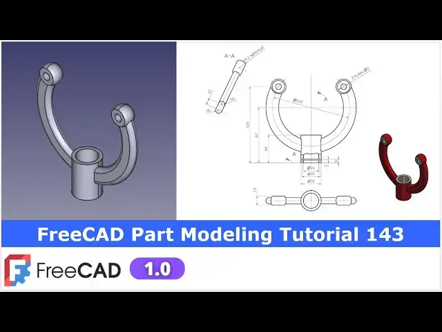
FreeCAD Part Modeling Tutorial | FreeCAD Tutorial 143 | 3D Modeling | Learn FreeCAD | Mechnexus |
Apr 24, 2025
#freecad #freecadtutorial #learnFreeAD
In this video I have explained How to Model Part in FreeCAD with the help of part design Workbench.
▶️ Join my channel membership and keep supporting my work:
https://www.youtube.com/channel/UCcn6z2whMaFu-_LDsEXCfVA/join
▶️ Visit my website for more info on FreeCAD-:
https://mechnexus.com/
▶️ Get my FreeCAD Crash Course for beginner-:
https://www.udemy.com/course/freecad-course-for-beginner/?referralCode=3BA9B526A12F96295D44
▶️ Download Source File of Tutorial-:
https://mechnexus.com/mechnexus-youtube-tutorial-source-file/
▶️ Buy Me a Coffee
I am very grateful that you watch my videos and I am constantly trying to improve the quality of the videos on this channel. If you'd like to help me do this, please consider supporting me so that I can to continue to produce content for your enjoyment.
👉 Help support this channel by buying me a coffee: https://ko-fi.com/mechnexus
Show More Show Less View Video Transcript
0:00
hello friends welcome to Freka tutorial
0:02
and in this tutorial we will model this
0:05
part and uh you can see that uh I have
0:08
already model it and uh I will show you
0:11
from the scratch how you can model this
0:14
part For this tutorial I'm using fread
0:18
version 1.0 So you must have at least
0:21
fread version 1.0 or a higher version of
0:24
a frecad So let's uh close this file and
0:28
create a new
0:30
file You can also visit my website
0:34
macexus.com where I write articles and
0:38
tutorials on freead and you can also
0:42
access my 3D part library of a free You
0:47
can download the part from here and you
0:50
can use in your projects with
0:53
modifications
0:55
You can also access my 2D drawing
0:58
library where you can uh download this
1:02
2D drawings and uh you can create 3D
1:06
models with respect to these
1:10
drawings You can also support me on
1:14
coffi.com You can buy me a cup of coffee
1:18
Your small support will uh help this
1:21
channels to grow and it will motivate me
1:24
to create more awesome content on uh
1:28
free CAD You can find my Kofi donation
1:30
page link in a video description as well
1:34
as you can also see my Kofi page URL on
1:38
this
1:39
header So let's come back to our
1:42
tutorial
1:44
So here I have created a new file and
1:46
now I will uh insert my body and let's
1:50
uh on the origin plane and uh start our
1:53
first
1:54
sketch So if you see our part
1:58
orientation So here first we will
2:01
uh create this half
2:04
profile on a front plane So select the
2:07
front
2:08
plane and click on the
2:12
sketch And
2:14
now go to the model tab and of the
2:17
origin plane So here we are seeing the
2:20
diameter of a 122 So here we will create
2:23
a three
2:24
diameter So select a circle tool and
2:28
create a three
2:32
diameter and let's constrain it So outer
2:38
diameter is of a
2:45
142 and let's drag it to the
2:50
inside Inner diameter is
2:54
of 122 and
2:57
uh mid one is of 122 and inner one is of
3:01
102
3:05
So first let's uh make this as a
3:11
construction and
3:13
let's this is the middle one of
3:18
122 and the inner one is of 102
3:24
Now let's move the dimensions to the
3:28
other
3:30
side because we will create our profile
3:34
here So here if you
3:40
see here is our origin which is this one
3:44
and if we
3:46
subtract 87 from 120 so we will get the
3:51
dimension So let's select a line tool
3:55
and uh create a
3:59
line and now we will fix this point So
4:04
select a smart
4:05
dimension and
4:07
here provide 120
4:11
minus
4:14
87 So this is of
4:18
33 So we have got this point but this
4:22
will be as a
4:24
construction and now let's move the
4:27
dimension on other side and now here we
4:31
will create two more
4:38
line and let's make this line
4:43
parallel Make this parallel with this
4:47
And now these two
4:52
line will be the construction one And
4:56
now here this 33 dimension actually we
5:00
want this
5:01
midpoint which is unconstrained So we
5:05
will fix this Select
5:08
the dimension 120 minus 87
5:15
So this is the point
5:18
Now let's move this point and uh let's
5:22
create three points here and which will
5:26
be coincident to this axis and this uh
5:28
construction diameter So here you will
5:31
see the option of a point Create three
5:34
random points
5:37
and select this and this and add a
5:40
coincidence Select this and this and add
5:44
a
5:45
coincidence Select this and this and add
5:47
a
5:49
coincidence Add a
5:53
coincidence Coincidence and coincidence
5:57
So we have got three points here and
6:00
three points here And now we will create
6:03
the threepoint arc Select the threepoint
6:06
arc and
6:11
uh here you can use the equal constraint
6:14
or tangency as well So I will use the
6:17
tangency and uh then I will select again
6:22
three point arc and select this outer
6:25
one and I will select this and this and
6:28
uh add a
6:30
tangency
6:32
Now let's close the
6:35
profile to draw the line by connecting
6:38
these two
6:39
points Same way
6:43
here So our profile is fully constrained
6:47
We will come out of the
6:48
sketch And
6:50
now
6:52
let's create the pad So here we will
6:56
create a pad of 10 mm
7:01
Press
7:03
zero Select the sketch and click on the
7:07
pad And
7:09
here we will keep it symmetric to the
7:13
plane and uh say
7:16
okay Now let's move to the next feature
7:20
and our next feature is to create a data
7:24
plane at a distance of 43
7:27
So let's press zero and on the origin
7:30
plane and uh we will select the top
7:32
plane and uh we will create our sketch
7:35
Select the top plane and click on the
7:38
plane and
7:42
here in a Z direction we will provide
7:45
the dimension minus
7:48
43 because we want it on a down side and
7:53
uh select okay And now off the origin
7:57
plane and rebuild our DATM
8:00
plane Now on this DATM plane we will uh
8:05
create circle of a diameter 32 So select
8:09
it
8:11
and create the
8:13
sketch And now here select the
8:17
circle create a circle Select a
8:21
dimension and provide it 32
8:25
Click on close Hide edit plane And
8:29
now we will add the material
8:33
here So to the distance of a 44 Select
8:38
it and click on the pad And here we are
8:42
not seeing anything because our
8:44
extrusion is on the wrong directions So
8:47
we will reverse it And here we will
8:50
provide the dimension of uh 44 and say
8:55
okay Now we will uh mirror this pad on
9:00
the other side So we will select our
9:03
first pad and click on the
9:06
mirror So you can see that fread
9:08
automatically took the reference and
9:11
mirror for us So say okay And now we
9:15
will create a fillet of 5 mm on
9:19
uh all the ages So click on the
9:23
fillet So here our thickness is
9:28
of 10 mm So 55 mm fillet will not work
9:32
So we will provide
9:35
4.99 And uh let's select this
9:42
age Same way select inner age
9:49
Select this and
9:51
uh
9:55
this this and
10:00
this Now say
10:03
okay So you can see that uh fillet is
10:08
created Now we will create a datam plane
10:12
Press zero for isometric view and let's
10:15
on our origin plane So we will create a
10:20
DATM plane at a distance of
10:24
51.3 So we will cross check this
10:27
dimension So let's go to the sketch And
10:31
here we wanted to create a data plane at
10:34
this point So let's uh measure the
10:37
distance from this point to this point
10:41
So it is a 51.3 Correct so let's uh
10:46
close it
10:50
And here we will
10:52
uh select the plane and click on the
10:55
data plane and provide the distance of
10:58
uh 51.3 in a Z
11:04
direction and make it front So we are
11:08
getting our plane at exact location and
11:11
say okay And now on this plane we will
11:15
create our
11:17
sketch Press zero for
11:20
isometric And now let's off the origin
11:23
plane And uh select our sketch And
11:28
uh so we have a selected the plane And
11:32
now we will uh create our
11:36
profile
11:38
So let's
11:40
uh start creating by switching to the
11:43
wireframe view
11:45
first and also of this datam
11:49
plane And
11:53
now if we see our model so here we have
11:58
found a distance of 33 So here we will
12:02
uh project this ages So click on the
12:08
project and
12:10
uh rotate it and project this edge and
12:14
project this
12:16
edge And now we will uh create a
12:27
circle and uh
12:30
let's constrain it to the diameter of a
12:35
24 Select the smart dimension and
12:38
provide it a 24 And
12:41
now we will
12:44
uh make this circle coincident with this
12:49
axis And now here we will uh make this
12:53
uh circle as a
12:55
construction So select it and make it
12:58
construction And
13:01
now if you see here so here is a radius
13:05
R12 is
13:07
given So let's first move our dimension
13:11
and we will create a threepoint
13:15
arc Select it and uh create a threepoint
13:20
arc And
13:24
now move
13:29
it and let's constrain this
13:34
center provide it a distance of 33
13:39
because if you subtract this 87 from 120
13:44
So our construction circle is a
13:47
constraint And
13:53
now let's create a vertical
13:57
line and which will pass through this
14:00
center because we will create a revolve
14:03
cut So let's rotate our model and
14:08
uh select line tool and create a line
14:14
and make this line coincident with this
14:17
circle center and make it coincidence
14:19
Switch to the right And now let's make
14:22
this line horizontal And
14:25
now let constrain this line So to
14:29
constrain this line we will select this
14:30
point and this line and add a
14:33
coincidence Select this point and this
14:35
line and add a
14:37
coincidence So this line is constrained
14:40
and now we wanted to constrain this arc
14:43
So we will select a line
14:46
tool Select a line and same way
14:51
here So this is the fully constrained
14:55
profile And now we will revolve this
14:58
profile around this axis So let's uh
15:01
exit the
15:03
sketch And now let's uh switch our model
15:07
to the shaded
15:15
view Now select revolve
15:18
tool So we are not seeing anything So we
15:22
will click on select reference and we
15:24
will select this
15:26
line So you can see that
15:31
uh our feature is created Now
15:37
here say okay So if you see that uh this
15:41
is
15:42
the out of this
15:45
face So we will edit our sketch profile
15:50
This will be the
15:53
24 So let's fix
15:57
that So
16:00
here first we will check this the
16:02
thickness So this
16:05
thickness is showing the 10
16:09
mm And uh we have made a coincidence
16:13
that's why So we will edit our sketch
16:15
and fix this issue
16:22
Now we will make this symmetric So click
16:25
on the
16:27
symmetric Now if you see that uh this is
16:30
R12 but here in a top view the thickness
16:33
is given is of 14 mm which I misread
16:36
here So here we have given the 14 mm So
16:39
we will uh select the dimensions tool
16:42
and uh provide it of 14 mm and uh we
16:47
will come out of the
16:51
sketch Now let's uh switch to the flat
16:58
lines first Switch to the shaded and
17:00
then flat lines So now our revol is
17:04
automatically got updated and now it is
17:06
looking with respect to the our
17:10
reference because this face is uh ahead
17:14
of this face Now let's uh mirror this
17:18
features to the other side So select the
17:22
our revolution and now click on the
17:25
mirror and uh let's uh select the
17:30
reference and uh select the YZ plane So
17:34
you can see that it is mirror on the
17:36
other side Say
17:39
okay Now our uh next feature is to
17:42
create a
17:44
hole these two holes So here is a two
17:48
hole of a D 9
17:50
So I will select the face because this
17:53
phase and this phase are at the same
17:55
level Click on the
17:58
sketch and
18:00
here we will simply project the diameter
18:04
and uh create a
18:07
circle So let's uh project
18:10
it so that we get a
18:14
center And
18:20
now select the circle tool and directly
18:23
create a two circle on this center point
18:28
Select a smart dimensions and here is of
18:30
diameter
18:32
9 So provide it a 9
18:37
mm And here instead of providing the
18:40
dimension we will select this and this
18:43
and made it equal Now press
18:47
zero Come out of the
18:50
sketch Select the sketch And now here it
18:54
is a drill hole In most of the my
18:56
tutorials I made this a drill hole with
18:59
the pocket tool But now I will use the
19:02
hole wizard And here is our drill size
19:05
is of 9 mm and I simply say it through
19:09
all and we will say okay So our hole is
19:12
created and
19:14
now let's uh create our next
19:20
feature Our next feature is to create
19:24
this groove
19:27
cut
19:28
So we will on the origin
19:32
plane and select this front plane and
19:35
click on the
19:38
sketch and uh we will uh hide our origin
19:41
plane and we will switch to the
19:44
wireframe
19:47
view So here the first thing which we
19:50
will do is to project the
19:53
edges Select this and this And now we
19:58
will select a polyline
20:02
tool and let's create a rough
20:16
profile And now let's add the relevant
20:21
relations So first make this line
20:24
vertical If you are not seeing the
20:26
constraint symbol like this line is a
20:28
vertical then you have to provide it
20:31
select it and provide it horizontal
20:33
Select it and provide it vertical and uh
20:36
this is the
20:38
horizontal
20:40
Now let's move
20:46
it So let's see uh our loop is closed or
20:50
not So we will come one time out of the
20:53
sketch So here we are seeing this line
20:56
Now let's uh constrain our
21:05
sketch So first we will uh fix this
21:09
point which is of a 12 mm Select a smart
21:12
dimension
21:22
And now let's fix this
21:26
point which is of 14
21:29
mm And uh this is of 2
21:35
mm And from this point to this
21:41
point is of a 6
21:45
mm And now we will select this point and
21:50
this point and add a vertical
21:53
relation So here we have the conflict So
21:57
we will uh delete
21:59
it So here we will specific select the
22:03
vertical
22:05
constraint because
22:07
sometimes if you directly click on this
22:09
it will not work sometimes means it is
22:13
very hard chances is that uh it
22:16
miscalculate it but uh in more than 90%
22:19
of cases it works if it is not work then
22:22
you select a specific horizontal or
22:25
vertical constraint like I did in this
22:27
case now our uh sketch is fully
22:32
constrained click on
22:35
close and we will keep our model to the
22:38
wireframe view and we will select our
22:40
sketch and click on the group
22:43
feature And uh it automatically took the
22:46
Zaxis my
22:48
reference Say
22:52
okay Now let's press our model to the
22:56
isometric
22:58
view And
23:01
let's give the color because our model
23:04
is completed And we can see that uh our
23:08
free model is exactly matching with our
23:11
reference isometric model Let's select
23:15
the body and uh go to the
23:17
appearances and
23:19
here we will go to the custom
23:22
appearances and click on the color and
23:25
here let's uh give the
23:30
color So close it
23:36
and say okay Now you can see that we
23:40
have given the exact red color And now
23:43
let's switch to the part
23:48
workbench And now we wanted to give the
23:52
different color to the face So I will
23:56
select the face And here you will see
23:58
the option of a color per
24:01
face And
24:03
here select this face this
24:07
face this
24:09
face this face and also rotate on the
24:12
other side Select this face this face
24:16
and uh this face and this face So you
24:19
can see that
24:21
uh uh
24:24
separate faces has been selected and now
24:28
switch to the bottom side and click on
24:30
the custom appearances So instead of a
24:32
red I will uh give this white color and
24:36
say
24:39
close Say okay Press zero So you can see
24:44
that
24:47
u it is a exact replica with respect to
24:50
the reference So this is how we have
24:54
modeled this part with the help of a
24:56
part design workbench and we have also
24:59
given the color with respect to the our
25:02
uh
25:03
reference drawing and uh it is matching
25:05
with our isometric view So this is all
25:08
about this tutorial Thank you for
25:10
watching and thank you for your valuable
25:12
time
#Visual Art & Design
#CAD & CAM
#Education
#Sculpture
#Computer Education