Up next in 10

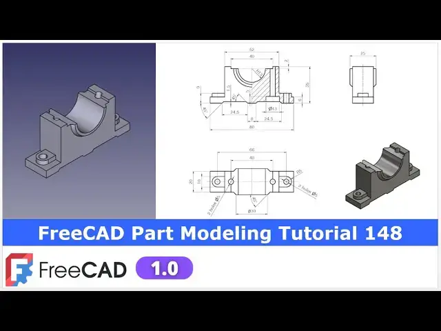
FreeCAD Part Modeling Tutorial 148 | FreeCAD Tutorial | 3D Modeling | Learn FreeCAD | Mechnexus |
Apr 25, 2025
#freecad #freecadtutorial #learnFreeAD
In this video I have explained How to Model Part in FreeCAD with the help of part design Workbench.
▶️ Join my channel membership and keep supporting my work:
https://www.youtube.com/channel/UCcn6z2whMaFu-_LDsEXCfVA/join
▶️ Visit my website for more info on FreeCAD-:
https://mechnexus.com/
▶️ Get my FreeCAD Crash Course for beginner-:
https://www.udemy.com/course/freecad-course-for-beginner/?referralCode=3BA9B526A12F96295D44
▶️ Download Source File of Tutorial-:
https://mechnexus.com/mechnexus-youtube-tutorial-source-file/
▶️ Buy Me a Coffee
I am very grateful that you watch my videos and I am constantly trying to improve the quality of the videos on this channel. If you'd like to help me do this, please consider supporting me so that I can to continue to produce content for your enjoyment.
👉 Help support this channel by buying me a coffee: https://ko-fi.com/mechnexus
Show More Show Less View Video Transcript
0:00
hello friends welcome to Frea tutorial
0:02
and in this tutorial we will model this
0:04
part as you can see that uh I have
0:07
already modeled it and it is a matching
0:10
with our isometric uh view so this part
0:14
is basically a bearing housing which we
0:16
can see that uh and this is the bottom
0:19
portion and these two holes are for the
0:22
mounting and there will be the top one
0:24
as well
0:26
so we will create this part from the
0:29
scratch and uh for this tutorial I'm
0:32
using the frecad version 1.0 so you must
0:35
have at least fread version 1.0 or
0:39
higher so let's uh close this file and
0:43
uh I will create a new file and show you
0:45
from the scratch how you can read the
0:47
dimension and create this model
0:50
you can also visit my website
0:53
macexus.com where I write articles and
0:57
tutorials on a freecad and you can also
1:01
access my 3D part library of a free CAD
1:06
you can download the part from here and
1:09
you can use in your projects with
1:12
modifications
1:14
you can also access my 2D drawing
1:17
library where you can u download this 2D
1:21
drawings and uh you can create 3D models
1:26
with respect to these
1:29
drawings you can also support me on
1:33
coffi.com you can buy me a cup of coffee
1:37
your small support will uh help this
1:40
channels to grow and it will motivate me
1:43
to create more awesome content on uh
1:47
free cat you can find my Kofi donation
1:49
page link in a video description as well
1:53
as you can also see my Kofi page URL on
1:57
this
1:58
header so let's come back to our
2:01
tutorial
2:04
so here I have created a new file and I
2:06
will insert my body and on the origin
2:09
plane now let's start reading our model
2:13
so if you see our model so major portion
2:17
will come on the right plane and we will
2:19
extrude it to the
2:21
symmetric which we can uh see in a top
2:25
view as well that it is a symmetric one
2:28
feature on left hand side or also on the
2:31
right hand side so we will also use the
2:32
mirror
2:35
tool now let's uh select the right plane
2:38
and click on the
2:41
sketch and off the origin plane and
2:45
here first we will uh create this outer
2:50
boundary so let's uh select a polyline
2:54
tool to draw the continuous profile so
2:56
first we will create a horizontal line
3:00
and
3:02
then create a rough profile and then we
3:05
will provide the relevant
3:07
constraint so this is the rough profile
3:10
and let's start constraining so this
3:12
will be the vertical this will be the
3:16
horizontal and uh this will be the
3:19
vertical and uh this also be the
3:23
vertical so this is the approximate
3:25
profile and
3:27
now we will constrain it and uh our part
3:31
is a symmetric with this axis so we will
3:34
provide a symmetricity constraint
3:37
so choose the symmetricity constraint
3:40
option and uh select this point and this
3:43
point and this axis and here I will
3:47
provide the dimension of 80 mm
3:51
and
3:53
now let's uh provide the 6 mm
3:57
dimension and here we will uh select
4:00
this and this and add equal relation and
4:04
now this point also to be symmetric so
4:09
we will again select symmetricity
4:12
constraint select this
4:19
point and select the
4:22
axis now let's uh provide this 35 mm
4:27
dimension which is the overall height so
4:30
select this
4:31
point this point and uh provide the 35
4:36
mm and let's see what is the unconstrain
4:40
so if we constrain this width which is
4:42
of a 52 mm select a smart dimension and
4:47
provide a
4:50
52 and let's move this 6 mm dimension so
4:54
we have a fully constrained our base
4:56
profile and now come out of the
5:02
sketch press zero and now we will uh
5:05
extrude it to the distance of 20 mm
5:10
which we can see here so select the
5:13
sketch click on the pad provide the 20
5:17
and keep it uh symmetric to the plane
5:19
and say
5:21
okay and now let's see the isometric
5:24
view so we have created the base profile
5:27
now we will
5:29
first finish the material addition
5:31
operation as much as possible so we will
5:34
add the material on the left hand side
5:36
and then we will mirror it to the right
5:38
hand side so select the face and click
5:41
on the sketch and now
5:44
here we will press
5:47
zero and now we will rotate our model to
5:50
the top view and here we will switch to
5:53
the wireframe and we will uh project
5:56
this age click on the project
5:59
geometry so age is projected and now I
6:02
will uh select uh threepoint
6:07
arc and uh make this and this
6:12
coincidence and now we will create one
6:15
horizontal
6:19
line and then we will create a two
6:23
vertical
6:25
line select this and this
6:28
select
6:29
this and this and now let's first make
6:34
this line
6:37
vertical and provide the tangency
6:41
constraint same way provide the tangency
6:45
constraint and
6:47
now let's
6:50
uh constrain it with the dimension
6:53
reading so here diameter is given 10 so
6:56
we will select a smart dimension and
7:00
provide it a 5 mm
7:02
radius and uh center to center distance
7:06
is of 66 so from origin let's select a
7:11
dimension select this point and our
7:14
origin point and here we will simply 66
7:19
/
7:21
2 and now our profile is fully
7:25
constrained now we will uh select the
7:27
sketch click on the pad and add the pad
7:30
of uh 3.5
7:33
mm say okay and now we will mirror this
7:38
on the other side so click on the
7:40
mirror select uh
7:43
reference and uh select this mid plane
7:47
and say
7:49
okay so we have a mirror it on the other
7:52
side and now let's move to the next
7:55
feature next feature is to create this
7:58
cut whose detail we can see in a front
8:01
view so here we will create this profile
8:05
and we will remove the material and then
8:08
we will mirror it on the other side with
8:12
respect to our mid plane
8:15
so here I will select the face and click
8:18
on the
8:19
sketch and here I will again select a
8:22
polyline
8:25
tool let's select a poly line and we
8:27
will create a rough
8:35
profile and
8:38
now let's uh constrain it so from origin
8:42
it is 4 mm select a smart dimension
8:45
select this and uh this and uh provide
8:49
the 4 mm and now provide the horizontal
8:53
line
8:59
24.5 and uh let's uh provide the angular
9:06
dimension so this is of a
9:10
45 and
9:12
uh this is of a
9:15
45 and now let's uh define the
9:19
height of
9:24
1.5 which is a 1.5 45 on the both the
9:27
side and this is a
9:29
24.5 say close simply select the sketch
9:34
click on the pocket and simply set it
9:37
through wall and now we will mirror this
9:40
on the other side say
9:42
okay now select the pocket and click on
9:45
the
9:46
mirror so you can see that a frecad is
9:50
very smart it automatically to
9:53
the Z axis and
9:56
uh created our mirror
10:02
so let's say
10:03
okay and
10:06
now let's create the next feature so
10:09
next feature is to create a cut of a 40x
10:13
20 rectangle so select the face and
10:16
click on the
10:18
sketch click on the project geometry
10:21
project this age and uh select a
10:24
rectangle tool create a rectangle and
10:27
now mirror it so click on the
10:30
symmetricity select this and this and uh
10:34
say the axis now select the smart
10:38
dimension provide it uh 40 and
10:43
uh vertical is of uh
10:47
two now close it and we will uh remove
10:50
the material
10:55
just simply say it through all and say
11:00
okay so let's save our part we have
11:03
forgot to save
11:08
it i will give the revision
11:11
R1 and now let's move to the next
11:15
feature which is to create a cut of
11:19
diameter 26 so we will select the face
11:23
and click on the sketch and here we will
11:28
uh project this
11:31
age and
11:33
now I will create a
11:36
circle and let's provide the coincidence
11:39
relation by pressing the control key and
11:41
select this point and line and add a
11:44
coincidence same way here say it a
11:48
coincidence and this is R13 so our
11:51
diameter will be the
11:55
26 say
11:58
close now we will create a
12:03
cut simply say it through all say
12:09
okay and now let's uh create a next
12:12
feature so our next feature will be a
12:16
revolve
12:17
feature here we will create this profile
12:21
and we will uh revolve around the
12:25
axis so for this we will uh select the
12:28
face and create our
12:31
sketch and now let's uh see the
12:35
orientation of our parts and now we will
12:37
make this top face normal and uh we will
12:40
project this edge click on
12:43
the project edges and let's create a
12:47
rough
12:49
profile select a line tool first create
12:52
a line which will be
12:54
collinear so
12:57
here we will again select a line tool
13:01
and
13:03
uh create a rough profile and we will
13:08
constrain it so this should be the
13:10
horizontal so now we will uh define this
13:15
point from the
13:18
axis to the distance of a 15 mm
13:24
and this point from our
13:27
x-axis is of a
13:32
12.5 so this is the our
13:36
profile if you see it now we will
13:40
revolve it so select the sketch click on
13:43
the
13:45
revolve and now
13:48
here it is created a 360° revolve but we
13:53
do not want 360 we want
13:58
180 now it is going to the top so we
14:02
will click on the reverse so that it
14:05
will be get reverse and we have got our
14:08
feature and
14:09
now this feature is the same on the
14:12
other side which we can see in the top
14:14
view as well as in the side view so if
14:18
you see the side view this feature is
14:20
matching now we will mirror it select
14:24
the
14:26
mirror and here select reference and in
14:30
a reference we will define this YZ plane
14:33
as as our reference so you can see that
14:36
a feature is created say
14:40
okay now let's move to the next feature
14:44
next feature is to create the
14:46
counterboard holes so we will select
14:50
this bottom face and click on the sketch
14:54
and now we will create a two
14:58
circle one is on the left hand side and
15:00
other is on the right hand side and we
15:02
will use the symmetricity constraint
15:05
select both the points and the axis
15:08
select a smart
15:10
dimension select this and this and uh
15:14
provide the dimension of 40
15:16
mm and now define the diameter
15:23
13 which we can see here diameter 13 say
15:27
okay now I have defined one diameter so
15:30
I will close it and made it equal now
15:34
let's create a counterboard holes so
15:37
here we will select our sketch and click
15:41
on the hole wizard tool and in whole
15:45
wizard we will define first our drill
15:47
through drill so here is a diameter 13
15:51
and if you see the top
15:53
view so here is the given two holes of a
15:56
diameter five so here we will define our
15:59
diameter five and uh we will make a true
16:03
all so you can see the true all hole is
16:07
created now we have to define the
16:09
counter board so whole option select
16:12
counter board and here we will define
16:14
the diameter and depth so obvious our
16:19
diameter is of
16:20
13 and uh depth depth is given is a 5 mm
16:26
so create a file so you can see that a
16:29
counterboard hole is created from the
16:31
bottom and it is a opening on the
16:33
top
16:35
now let's switch to the isometric view
16:38
and uh we will create two holes so here
16:43
is a two holes of dia five which is very
16:46
simple to create i can create one hole
16:48
here and then use the mirror tool but I
16:51
will make it in a single sketch so
16:53
select the face and click on the
16:55
sketch and uh click on the project
16:58
geometry project this radius and this
17:02
and uh create a
17:05
circle on both the side and this is of a
17:09
diameter
17:10
five provide the 5 mm and now select
17:15
this and this and make it equal and now
17:19
let's use the whole wizard option select
17:21
the
17:22
hole and uh here we will simply define
17:26
the drill drill of 5 mm and uh say it
17:30
through wall and say
17:33
okay so you can see that we have
17:37
successfully modeled this part from the
17:39
scratch now let's apply the color with
17:43
respect to the our reference model so
17:45
here I will select my body and go to the
17:49
appearances and
17:51
here we will go to the custom
17:53
appearances and go here diffuse color
17:56
and here I will adjust my setting so
18:00
that it this color should match with our
18:03
body so I am taking it
18:06
approximate and move it and close it so
18:10
you can see that more or less the color
18:13
is matching
18:15
and this completes our model so this is
18:20
the very interesting model which is very
18:23
simple as well as to understand
18:27
the major feature of a fread like a
18:30
mirror pocket revolution hole wizard and
18:34
most important how to create a
18:35
counterboard holes so this is all about
18:39
this tutorial thank you for watching and
18:41
thank you for your valuable
18:44
[Music]
18:48
[Laughter]
18:48
[Music]
19:00
time heat
#CAD & CAM
#Training & Certification
#Computer Education