live_tv
Livestream Starting Soon
00
Hours
:
00
Minutes
:
00
Seconds
Up next in 10

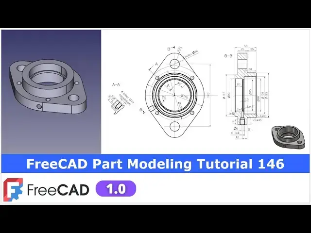
FreeCAD Part Modeling Tutorial 146 | FreeCAD Tutorial | 3D Modeling | Learn FreeCAD | Mechnexus |
Apr 28, 2025
#freecad #freecadtutorial #learnFreeAD
In this video I have explained How to Model Part in FreeCAD with the help of part design Workbench.
▶️ Get my Complete FreeCAD Course : From Zero to Expert !
https://ko-fi.com/s/1ab4385434
▶️ Join my channel membership and keep supporting my work:
https://www.youtube.com/channel/UCcn6z2whMaFu-_LDsEXCfVA/join
▶️ Visit my website for more info on FreeCAD-:
https://mechnexus.com/
▶️ Download Source File of Tutorial-:
https://mechnexus.com/mechnexus-youtube-tutorial-source-file/
▶️ Buy Me a Coffee
I am very grateful that you watch my videos and I am constantly trying to improve the quality of the videos on this channel. If you'd like to help me do this, please consider supporting me so that I can to continue to produce content for your enjoyment.
👉 Help support this channel by buying me a coffee: https://ko-fi.com/mechnexus
Show More Show Less View Video Transcript
0:00
hello friends welcome to free tutorial and in this tutorial we will model this part as you can see that uh I have
0:07
already model it and uh you can see that uh our freet part is matching with a
0:14
isometric view of a reference drawing now we will uh read the dimensions of
0:20
this top view and section view and we will create this part from the scratch
0:26
so I will close this file and create a new file if you want to learn free CAD from
0:34
the scratch then you can buy my complete free cat course from zero to expert this
0:40
course also available on Udemy but uh problem is that uh UDMI only give me the
0:48
37% of a core selling you can see here user had paid $15 but I have only got $5
0:59
so after minus of a taxes I get the pennies on each course
1:05
selling if you wanted to see the review of my course you can go to the Udemy and
1:12
s search for the free CAD and you will see my course complete free CAD course
1:17
from zero to expert and this course is took by the more than 2,000 students and
1:24
I have got the rating of a 4.1 for the demo lectures you can expand
1:31
it and uh see the demo lectures and the course structure but I will request you
1:39
if you found my course interesting and the reviews of the other student on
1:46
Udemy then I would request you to buy my course from the my coffee shops because
1:55
if you buy from here it will help me a lot so once you buy my course you will be
2:03
redirected to the Google drive and here is the my course complete free course
2:09
from zero to expert go inside and uh the
2:14
sections I have shown you on my Kofi shop page so exactly same lectures under
2:23
the section is created for example section one is a introductions to free
2:30
1.0 and what is new in a freecad 1.0 so if you go to the section one so there
2:37
are the 18 lectures and if you go inside of the sections one you will find the 18
2:44
lecture total and once you go to the lecture one you will find a video file
2:50
which you can download to your system and you can watch it and uh this course
2:57
is uh updated on a equal interval of a time once the new feature is came and uh
3:04
once you purchase the course you have the lifetime access to the course and in
3:10
the case of any doubt any query you can mail me at admin
3:17
rate.com at the end you will find one uh video which is a promotional video you
3:23
can watch the video and uh take the whole overview of the course you can
3:29
also explore my shop where you can uh download the tutorial source file and
3:35
some interesting projects on free CAD you can find my course link on my
3:42
YouTube channel you can see the course link and uh you can also find my Kofi
3:48
course page link on uh pin comments and uh video descriptions so buy my course
3:57
and uh keep supporting my free CAD works your small course purchase will uh help
4:03
me to grow this channel and it will also motivate me to create more awesome
4:10
content on free cat so please check out my course on a free
4:17
CAD from uh 02 expert so here I have created a new file
4:22
and I will insert my body and on the origin plane and as per part orientation
4:29
first we will create this uh base profile on the top plane so select the
4:35
XY plane and click on the sketch and now go to the model tab and hide the
4:43
origin plane and now here let's uh switch to
4:48
the our main view and here we will uh
4:54
create first a circle so let's uh create a
4:59
circle and uh we will uh make this circle as a
5:07
construction and now select uh smart dimension and
5:13
provide uh 160 dimension and now we will create these two arc so we
5:23
are uh creating our part as per the isometric view so here we will create
5:31
these two arc and uh just imagine that it is a 90°
5:38
rotated so let's uh create
5:43
a threepoint arc on uh right and uh left hand side and now here first thing we
5:52
will do is to make a coincidence relation with the arc center and the
5:58
axis similarly on the other side say coincidence and
6:05
now we will move this point little
6:13
bit and now we will create one threepoint arc on the top and one is on
6:19
the bottom select it and uh create the two
6:27
arc and now let's uh add a coincidence relation with our origin select it and
6:34
add a coincidence relation with our origin now here we will
6:40
uh make this two arc symmetric with the axis as it is the distance of 170 so
6:49
let's uh first we will make it symmetric and then add a dimension of
6:55
170 so arrow is added which means that uh it is a symmetric and it will move in
7:01
equal proportions once we move the points now let's uh give the
7:10
dimension let's give the dimension of uh 170 which we can see here and
7:18
now let's give the radius value which is
7:23
R30 so select it and uh give it a
7:30
30 and now select this and this and uh made it
7:36
equal now let's move the points and
7:42
uh now let's make this and this as equal
7:49
and also make it uh equal now
7:55
here we will uh create a
8:00
line at the top bottom which will be the four line and then we will add a
8:05
tangency which are this one 1 2 3 4 now let's uh select a line
8:13
tool and create a line by joining these two point select line tool and uh create
8:22
a line by joining two points select this and this and this here this now let's add a
8:31
tangency relation so first let's uh select this line and arc and add a
8:37
tangency select this and this and add a tangency select this and this and add a
8:45
tangency and here select this line and arc add a tangency so we have added the
8:52
four tangents and now we will add the four tangent on both the arc two on the
8:58
left and two on the right so we will repeat the same procedure make it tangent select it and
9:07
uh make it tangent similarly here on the right side make it tangent and select
9:14
this and uh make it tangent so you can see that uh our profile is fully
9:20
constrained let's come out of the sketch and here click on the
9:27
pad and provide 25 mm which we can see here and say okay so
9:37
we have created our first feature so let's first uh save our
9:49
part now let's create the next feature so
9:55
here we will select this bottom face and uh on a bottom face we will create this
10:02
diameter 115 and then extrude it in isometric this bottom face is not
10:09
visible but we can clearly see in the section view and also on the top view we
10:14
can see the hidden lines now I have selected the face and now I
10:20
will uh create a sketch so it is very simple just uh create a circle and uh
10:28
select a smart dimension and uh provide it a diameter 115 now let's close it and
10:37
uh create a pad of 8 mm so select the sketch click on the
10:43
pad if you subtract the this dimension from the overall you will get it so
10:52
here is a 8 mm now press zero for
10:59
isometric and if you see the isometric so we will create this uh major outer
11:04
diameter so we will select the top face and click on the sketch and here click
11:10
on the circle and uh provide the diameter
11:15
of 122 and click on the close and create a
11:23
pad of 25 mm select it and uh provide it a 25
11:29
mm and now if you see the section view so there
11:34
is a group profile now we will create the group profile and
11:40
here just imagine that uh this is the rotated to the 90° and now here I will
11:48
on the origin plane and here I will select the right plane which is a YZ plane and uh click on the sketch so here
11:57
we are on the right orientation and let's off the model
12:04
origin planes and let's switch to the wireframe for the better sketching and
12:12
now we will uh create the
12:18
sketch so here we have the origin here so we will
12:25
uh select a line tool and we will create a line on the axis and now we will uh
12:34
use the polyline tool to create a rough profile and then we will
12:44
uh constrain it so here the profile is created and now
12:50
we will start from here so here is a horizontal this is the vertical this line having no relation so we will
12:57
provide data horizontal constraint and this with a vertical
13:03
constraint and this become the horizontal constraint and this is
13:09
also horizontal now let's provide the dimension so
13:18
first provide the this dimension which is a 51
13:25
and this is of
13:35
33 and let's uh constrain this inner
13:41
one select a smart dimension select this point and this point and provide it uh
13:50
42.5 and uh this is of
13:59
45 and uh this line is of uh 20
14:08
mm now let's move the dimension and uh let's check what is the unconstrained so
14:15
if we move that total height is unconstrained so
14:21
here we will uh do one thing we will project this
14:28
age at a bottom and at a top so on the top I will
14:35
uh select this point this axis and this point and add a
14:42
coincidence relation so here we are seeing the conflict press Ctrl Z and now
14:48
let's move to the right view here and now let's uh
14:56
move the dimension and now select the point and this one and add a coincidence so here it got a coincidence relation
15:05
and now let's uh again switch to the right
15:13
view and now we have to constrain the total
15:19
height and now here uh total height is of 58 so I have given the 58 you can do
15:26
one more thing instead of giving a dimension you can
15:32
uh simply add a relation by selecting this point and line and add a
15:38
coincidence so here we are seeing the conflict so now let's move this
15:44
dimension and select this point and this line add a coincident so sometime what's
15:52
happen instead of a point axis work get selected so we have the fully
15:58
constrained profile and let's come out of the sketch and now here we will uh click a
16:06
group tool and here we will define our own axis so here I will use the Z
16:12
axis or you can select this vertical line of our sketch say
16:20
okay now press zero for isometric view and if
16:25
you see our model on a top view we can see here one
16:32
hole and here we can see the hole which is a
16:40
G1X4 and uh for this if you see from
16:45
this uh plane it is a 30° so we have to
16:51
create a DATM plane at a angle of 30° from this plane so let's
17:00
create a DATM plane now first uh on the origin plane
17:07
and here we will uh select the plane and we will uh
17:14
create our uh datam plane at a distance of 30° so
17:21
let's press zero so now here reference we will select the Z
17:28
axis and click on the data plane so you can see that uh our datam plane is
17:34
created along the xy and now we will uh rotate
17:40
it so that we get uh this 30° angle so now on the
17:46
x-axis provide the value - 60°
17:52
so here between the YZ plane which is our datam plane and our newly created
17:59
plane we will get a angle of 30° because if you minus 90 - 60 we will get a 30 so
18:07
now say okay now on the origin plane and here we will rebuild our data plane
18:14
click on recmp compute object and save our file now on this uh data plane we
18:20
will create our sketch so here we will switch our model to the
18:28
isometric view and here we can uh select
18:33
our uh datam plane and we can use the align to selection so it will
18:41
become normal our newly created data plane is normal and now we will uh
18:46
switch to the wireframe for the better sketching and let's off this data plane
18:53
and now create the profile and we will revol cut
19:00
it so first thing we will do we will click on the project geometry and project this
19:08
outer edge and now we will uh select a
19:14
line tool and uh create a line and let's first we will fix this
19:23
point so if you see here from the this age to the axis of the hole is of a 13
19:30
mm so I will select this point and this
19:39
point so let's first select this point and then select this point and provide
19:47
the 30 mm and
19:53
now we will create one more line select line tool and create one more line and
20:00
now again select a line which we can make a parallel or we
20:07
can also add a perpendicular relation and now we will uh if you zoom
20:14
so we have come here and now we will create a line with angle so create a
20:22
line and then create one more
20:27
line and let's make this shorter and
20:34
here we will uh create a line by joining these two points and here we can add a
20:43
parallel relation and now let's constrain our
20:49
dimension so first is a g1x4 you can uh
20:54
search the diameter value for the drilling
21:02
so this is radius is
21:07
of 5.945 so this is the value applicable to
21:16
the G1X4 here I have given the radius and now select this and this and provide the
21:25
18 mm and uh this angle here is not defined so we will
21:32
uh make it approximate to the 1 mm and let's move this 1 mm dimension
21:40
and uh total is of 50 we will take the value so that it should open in
21:47
a clear area so select the dimension and uh provide the 50 mm so
21:56
that it is opening in a clear area even though you can
22:01
uh make it 55 from the safer side and now let's
22:08
uh constraint this dimension so this is of diameter six so we will make this
22:16
line 3 mm so select the smart dimension and select it and uh provide the 3 mm so
22:23
you can see that uh our uh profile is made and uh this is
22:31
basically G1X4 use in a pipe thread so
22:37
now we will come out of the sketch and
22:44
here if you see let's try to create a group cut
22:53
here and uh let's say okay so wire is not closed so we have to validate our
23:00
sketch so go to the model and select the sketch and click on the validate option
23:07
and zoom our sketch and click on highlight troublesome
23:13
vertex so here let's see what is the
23:19
unconstrain so here we are uh not seeing anything on the
23:25
screen let's zoom it and uh again click on highlight troubleshoot vortex
23:32
so here uh I think that a problem is that we should make this point outside of a body so let's edit the
23:40
sketch and here we will delete this construction line and uh we will uh move
23:47
this line and now we will again project this
23:53
and uh let's add a small dimension of 2
24:02
mm so that it come outside of a body and now let's see what is the
24:09
unconstrain so this is the unconstraint so let's provide a suitable
24:15
relation and now let's see what is unconstraint so this axis so axis is a
24:23
13 mm from the age so select the smart dimension and uh select this and provide
24:30
the 13 mm now let's try to revolve it and uh
24:37
select the sketch click on the groove feature so now groove is created here
24:43
but the axis is uh not correct so we will select the reference so once you
24:51
select the reference your sketch will be visible and now we want to create the groove around our this line so click on
24:59
it so you can see that uh a groove is created and if you rotate our model we
25:07
can see that it is opening perfectly as per our reference drawing now press zero
25:15
for isometric view now if you see on a top view there is a
25:21
hole whose detail we can see in a section AA if you go in a section AA so
25:26
this is the M10 hole with a drill of 18 mm but the tapping is of 15 mm so we
25:34
will first select the top face and click on the sketch and if you see the top
25:40
view so here is a PCD of 135 so let's
25:45
rotate our model to this orientation and uh click on the circle and create a
25:51
circle and now here we will first make it a construction and let's add a diameter of
26:02
135 and now here is angle is of a 45 so we will also create a
26:09
line and also make it a construction and let's uh provide a
26:15
45° from the axis you can also provide this from this axis so let's provide a 45 so now we
26:24
have got this point and now we will uh create a
26:34
circle and uh select a smart dimension and uh provide it a 10 mm so we have
26:42
the diameter 10 circle now we will close it and here we will not use this pocket
26:50
tool to create the hole as I do most of the time here we wanted to create a
26:55
threaded hole now select the sketch and click on the hole wizard and here we
27:03
wanted to create four holes of M10 so from here I will select uh isometric
27:09
regular profile and here I will give the 10 mm depth depth I here I will give the
27:16
18 mm and uh go to the threaded and here I will select the
27:23
dimension and uh threaded dimension is of a 15 mm say
27:30
okay so you can see that uh hole is created
27:36
and now we will polar pattern this
27:41
hole because if you see
27:47
here there are the four holes so if you see the holes here so
27:54
that uh are in the hidden so this hole will be at a bottom side so we can
28:04
easily fix this with the attachment editor
28:10
now click on the attachment editor and here on the attachment editor instead of
28:16
uh this face we will delete it and we will define this bottom face select
28:22
reference and select this bottom and say okay
28:28
now let's rebuild it and also rebuild our
28:36
hole so you can see that hole is fully defined to the bottom face and now
28:42
select the hole and click on the polar
28:48
pattern and uh type the quantity
28:53
four say okay now switch to the top view and let's see the wireframe
29:00
view now you can see that uh these four holes which are hidden and are from the
29:06
bottom face is created now let's uh switch to the flat
29:11
lines so now we will
29:19
uh create these two holes of DI 26 which is very easy to
29:24
create and uh we will select this top face and click on the sketch and here I
29:31
will select the project geometry and uh project these two radius click on the circle create a
29:39
circle and uh select the dimension and provide the
29:47
26 and select this and this and uh made it equal say close select the sketch and
29:55
uh it is a plain drill hole so you can make with a cut select select the hole
30:01
and uh here select none and provide the diameter
30:09
26 and from here say it through all and say
30:14
okay now here at
30:20
uh section view we can see that chamfer of 1 mm on the edges so let's provide
30:30
the chamfer so here is a 1 mm chamfer on inside and outside so I will press
30:36
control key select these two edges and provide the chamfer of a 1 mm
30:43
similarly on the bottom
30:49
side this is the 1 mm
30:55
chamfer and uh this both also having the 1 mm chamfer so let's add
31:02
it click on the chamfer and say 1 mm
31:08
now here at the bottom side we will uh cross check this section
31:16
because this uh thickness looks not correct with respect to the
31:22
drawing so let's fix this so go to the pad and uh identify the feature so this
31:28
is the feature and now let's cross check the dimension so if we go here so it is
31:37
the 115 that is okay now we will uh cross
31:42
check it with the group feature so let's on the group feature and
31:50
uh move to the wireframe view and
32:02
here so this is for the hole we are not looking for this we are looking for that
32:10
internal cut so let's go to the flat
32:19
lines and now let's check here on the dimensions so this internal one is of
32:28
diameter 19 so we have to check this dimension so this will be the
32:37
45 let's uh switch to the wireframe so this should be the 45
32:43
because diameter is 90 so make it 45
32:52
and this one on the other side this is the of
33:03
102 102ide by two and click on
33:10
close and uh let's move to the last feature and hide this
33:15
sketch and uh from here switch to the
33:20
shaded view switch to the flat lines so now it looks okay this thickness so this
33:28
is how if you have modeled something and how we can uh rectify and how we can
33:34
rebuild it so we have successfully created this
33:39
model from the scratch and uh you can see that uh it is perfectly matching
33:44
with our uh reference isometric view so this is all about this tutorial
33:53
and this tutorial is uh for the beginner user to understand the how to create a
33:59
data plane pad grooves polar pattern chamfer and holes so I hope you have
34:06
enjoyed this tutorial thank you for watching and thank you for your valuable
34:28
time heat
34:52
heat heat
35:15
heat
35:33
heat hey Heat
36:04
and now we will come back to our tutorial