0:07
Hello everyone, myself Baradwas.
0:11
In this video I will discuss about how
0:15
to check power supply in Yoko Goa DCS
0:24
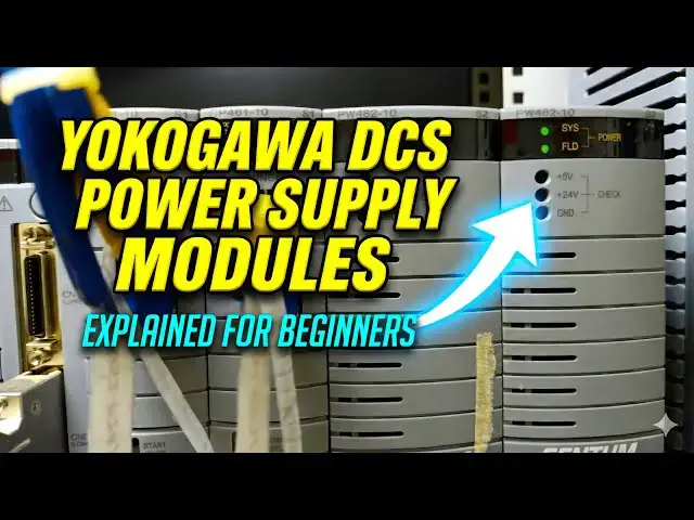
If you see in Yakugo DCS, we have two
0:29
power supply modules installed on the
0:32
right side. Okay, these two are the
0:39
and these power supply modules provide
0:42
two types of voltages.
0:46
Okay, if you see here we have
0:51
system syss system and FLD field. It
0:56
provides two power supplies. One for
0:59
system, second for field.
1:04
If you see there are modules installed
1:08
on the each node in DCS system, right?
1:13
These power supply modules provide plus
1:17
5 volts DC power supply to the IO
1:21
modules, CPU, serial communication
1:24
cards. Okay. IO modules like analog
1:28
input, analog output, digital input,
1:31
digital output or communication cards
1:34
like serial communication, mod bus, proy
1:38
bus, foundation field bus. Whatever
1:41
cards you will installed on the node,
1:44
these two power supplies provide the
1:49
voltage which is 5 volts for the
1:52
module's operation. Remember that and
1:56
also it will provide plus 24 volts DC
2:00
power supply to the field instruments.
2:05
whatever the field instruments connected
2:08
to the respective IO modules in this
2:12
node. Okay, for all those instruments,
2:16
these two power supply modules provide
2:19
the required power like let's say your
2:23
transmitter requires 4 to 20 milliamp
2:26
signal for its operation and also uh for
2:31
carrying the signal. For that purpose,
2:34
these two modules will provide the power
2:37
supply modules to your required uh IO
2:40
modules and then IO modules provide the
2:43
power to the connected field
2:48
Okay. If you have barriers
2:51
then uh it will go up to the barrier and
2:54
from the bar barrier again another power
2:57
supply may go to the field. that depends
3:00
on your design and configuration. Okay.
3:06
Now, uh we have to measure these two
3:10
voltages for all the power supply cards
3:14
installed in your DCS system. That is
3:17
very important. Either you have to check
3:21
monthly ones or quarterly ones or yearly
3:24
ones. That depends on your planned uh
3:29
procedures. Okay. Now I will show you
3:32
how to measure these two voltages.
3:35
You can use your multimeter. Connect the
3:38
negative probe to the ground and then
3:41
you have to place your uh positive
3:44
terminal across the 5 volts. Then we
3:47
will check the reading now. Okay. Now I
3:50
am measuring the system power which is 5
3:53
volt DC power supply. If you see it is
3:56
right now the voltage is around 5.12
4:01
volt DC power supply. These two modules
4:04
providing uh this mod sorry this module
4:06
is providing 5.12 DC to these modules.
4:10
Okay. Next I will measure the 24 volt DC
4:14
field power. See I connected 24VT DC and
4:19
right now the reading is 23.97
4:26
Okay. Like this you have to measure the
4:32
uh power supplies for all your CS.
4:38
if you see here this is my node one.
4:42
These two are my power supplies. Why two
4:47
Because these are critical modules.
4:50
Let's say I only have one module, one
4:54
power supply module. And the power
4:56
supply module is right. Let's say it is
4:59
damaged. Then what happens? Then the
5:02
power is not available to these modules,
5:04
IO modules, right? These are two, these
5:06
two are CPU, these two are communication
5:09
and these are the respective IO modules.
5:12
All will be down. That means your plant
5:15
is tripled if that happens. That is why
5:19
the critical modules will be minimum
5:23
two. If one fails, the second one will
5:28
Okay. If you see in this node one, this
5:32
is my node one. You can see these two
5:34
are CPUs are installed. Uh these two
5:37
power supply modules provide the system
5:40
power to these modules only.
5:44
Whatever the modules installed in the
5:46
respective node, this is my first node.
5:50
Okay, first line in simple terms.
5:54
These modules only receive the power
5:56
from these two power supplies.
5:59
And these two power supply modules
6:02
provide the required field instruments.
6:06
Okay, power that means that field
6:09
instruments must be connected to these
6:14
Let's say you have second node, third
6:20
then each node will have dedicated power
6:24
supplies. Two power supplies will be
6:27
there for each node and you can observe
6:31
on the right side. Uh okay.
6:35
uh during the design time okay the
6:40
engineers will calculate the required
6:43
power based on the connected
6:46
Let's say they connected some uh 50
6:49
instruments to these modules.
6:52
Then they will calculate the required
6:54
power consumption for those 50
6:57
Plus they will give some spare uh power
7:00
consumption 20% 30% that depends on
7:05
And they will calculate the modules uh
7:08
requirement, power consumption
7:11
Based on that they will have some figure
7:14
right? They will have some number.
7:17
Accordingly they will choose the
7:19
required power supply model.
7:23
But in maintenance we have to
7:26
periodically check these uh readings
7:31
system power and field power of
7:36
power supply module. Right now I uh
7:39
tested only for this left side power
7:42
supply module. Similarly, you have to
7:44
check for the right side power supply
7:47
module readings also. And then you have
7:50
to uh record in your uh documentation.
7:55
You have to repeat for all your DCS
7:58
systems. Okay? All your FCS. And if you
8:02
have multiple nodes, that means you have
8:04
multiple number of power supply cards.
8:08
You have to repeat the same test for
8:10
each and every power supply module. and
8:13
record your observations.
8:16
This is very helpful if the difference
8:18
is so much that means your card is going
8:24
So you can avoid these type of
8:28
if you have periodical maintenance
8:31
procedures in your plant.
8:35
I covered the basic testing of the power
8:37
supply modules and if you know any
8:41
better procedures, if you maintenance
8:43
procedures or protocols or any
8:46
suggestions and uh tips, you can share
8:50
with us through the comment section.
8:54
Please do like our videos and share uh
8:59
with your friends and colleagues.
9:02
Thank you for your support. I will meet
9:04
you in the next video. Thank you.