Up next in 10

In this CODESYS tutorial, we solve a classic PLC programming interview question: controlling 3 motors based on the number of active switches. This is a perfect example of combinational logic that every automation engineer should know.
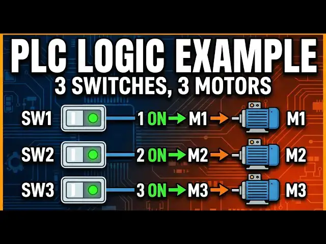
The Logic Challenge: We have 3 Toggle Switches and 3 Motors.
If ANY 1 switch is ON → Motor 1 turns ON.
If ANY 2 switches are ON → Motor 2 turns ON.
If ALL 3 switches are ON → Motor 3 turns ON.
Codesys PLC Course:
https://www.youtube.com/playlist?list=PLI78ZBihrkE1Fbt1rtkzuMhoiM_RbjWUz
#CODESYS #PLCProgramming #Automation #LadderLogic #IndustrialAutomation
Tags:
CODESYS,PLC programming,CODESYS tutorial,ladder logic examples,IEC 61131-3,automation engineering,industrial automation,codesys v3.5,boolean logic plc,3 switches 3 motors logic,plc logic challenge,how to program plc,combinational logic plc,codesys simulation,plc motor control,boolean algebra plc,codesys programming for beginners,smart logic plc,electrical engineering,scada,hmi,plc training,codesys,plc,programming,plc programming,codesys plc,plc switch
Show More Show Less View Video Transcript
0:00
[Music]
0:05
Hello everyone, welcome to automation
0:08
community. Today in this video we are
0:12
going to discuss an example in which we
0:14
will control three motors using three
0:17
toggle switches. So let's start.
0:22
PLC example three. We have three toggle
0:25
switches and three motors.
0:29
If any one toggle switch is on then
0:32
motor one will be on. If any two toggle
0:35
switches are on then motor two will be
0:38
on. If all the three switches are on
0:42
then motor three will be on. That means
0:46
if only one switch is on then motor one
0:50
will be on. That means if switch one is
0:52
on and other two switches are off then
0:55
motor one will be on. If switch two is
0:57
on and other two motor other two If
1:00
switch two is on and other two switches
1:02
are off then motor one will be on. If
1:05
switch three is on and other two motors
1:07
are off other two switches are off then
1:10
motor one will be on. And then if two
1:13
switches are on and the third one is off
1:16
then motor two will be on. And if all
1:18
the three switches are on then motor 3
1:20
will be on. So for this example we'll
1:23
use normally open contacts and normally
1:26
closed contacts. So let's move to
1:28
codices where we will draw a ladder
1:30
diagram. For this example
1:32
I will open codesses here.
1:46
Let's create a new project.
1:49
Let's select the template as standard
1:51
project and name as example
1:57
three. Okay.
2:02
After that we need to select latter
2:04
logic diagram and then click on okay.
2:10
Double click on PR PLCRG
2:14
and here we will draw the ladder
2:15
diagram. So firstly we will insert a
2:18
normally open contact here.
2:22
So this will be toggle switch one
2:26
to switch one.
2:29
So if switch one is on then
2:38
then here switch two and switch three
2:42
should be off. So we'll insert one more
2:45
normally closed contact here. So this
2:48
will be
2:50
switch
2:52
two
2:55
and then this will be switch three.
3:02
And then we'll insert a coil.
3:09
This will be motor
3:13
one.
3:16
So if switch one is on, switch two is
3:19
off, switch three is off, then the
3:21
signal will pass through this. As a
3:23
result, this motor one will be on.
3:28
Similarly,
3:31
when switch
3:34
two is on and switch one and switch
3:39
three should be off.
3:42
So use two more normally close contacts
3:44
here.
3:49
So this will be
3:54
switch one
3:57
and this will be
4:01
this will be switch three.
4:07
So if switch two is on then switch one
4:09
and switch three should be off then only
4:11
motor one will be on.
4:14
Then we need to connect here switch one,
4:17
switch two and switch three again here.
4:20
So for that I will show a trick here. So
4:22
we need to select all these switches
4:24
here. Switch one, switch two and switch
4:27
three and then insert a normally open
4:30
contact in paral.
4:33
So this will be switch three. So if
4:36
switch three is on then switch one and
4:40
switch two should be off. So we'll use
4:42
two normally close contacts here.
4:48
So this will be switch
4:51
one
4:53
and
5:01
this will be switch
5:04
two.
5:07
So for motor one to be on only one
5:10
switch should be on. Either switch one
5:13
or switch two or switch three should be
5:15
on and other two switches should be off.
5:18
If switch one is on, switch two and
5:20
switch three should be off. If switch
5:21
two is on, switch one and switch three
5:24
should be off. If switch three is on,
5:26
switch one and switch two should be off.
5:29
So when switch one is on the current the
5:32
uh the signal will pass through this and
5:34
then the signal will pass through this
5:37
only if when these two switches are in
5:39
false state because we have used two
5:41
normally closed contacts here to pass
5:44
the signal from here. These two normally
5:47
closed contact should be in false state.
5:49
Similarly when switch two is off the
5:52
signal should pass through this. So for
5:53
this switch one and switch three should
5:55
be off. Similarly when switch three is
5:57
on the signal should be passed from
5:59
here. So for that switch one and switch
6:02
two should be off.
6:04
After that we will insert a network
6:07
below. And here we'll insert a normally
6:11
open contact here
6:14
and this will be switch one.
6:21
And then we will so we need to turn on
6:25
motor two. So for for motor two to be on
6:28
two inputs should be on only two inputs
6:31
should be on. So we will insert one more
6:33
normally open contact here. So I will
6:37
click here
6:39
and then add a normally open contact. So
6:41
this will be switch two.
6:46
So if switch one and switch two and are
6:49
on then switch three should be off. So
6:51
we'll use normally close contact here
6:54
and this will be switch three. So switch
6:57
three should be on then the output will
7:00
be on. Then what will be on? Motor two
7:04
will be on. So this will be motor two.
7:07
Similarly here we have used two
7:10
switches. Switch one and switch two.
7:12
Similarly, switch two if switch two and
7:14
switch three are on and switch three is
7:16
uh switch uh switch one and switch three
7:19
are on and switch two is off then also
7:22
motor two will be on. So we will select
7:25
these two normally open contacts and
7:28
then insert
7:30
contact parallel.
7:32
So this will be switch
7:36
one.
7:38
If switch one and switch three are on,
7:42
so this will be switch
7:44
three are on and with that switch two
7:48
should be on. So we'll use normally
7:50
close contact here and this will be
7:53
switch
7:56
two. So switch two should be on. And
7:58
similarly we will select all these
8:01
contacts and insert
8:04
contact in parallel. Sorry,
8:07
we will
8:10
select all these and then insert a
8:12
normally open contact in part one. So
8:15
this will be
8:21
So this will be
8:24
switch
8:26
two
8:27
and then we will insert one more contact
8:34
and a normally closed contact. So this
8:37
will be switch three. So switch two and
8:41
switch three are on and switch one
8:44
should be off. Then only motor two will
8:48
be on
8:51
and then we will insert one more network
8:53
below here. So when all the three
8:56
switches are on then motor 3 will be on.
8:59
So in this case we will use three
9:01
contacts in series and a coil.
9:06
So for motor 3 the ladder diagram is
9:09
very simple. So this is switch one.
9:15
Then we have switch two.
9:20
Then we have switch three.
9:24
And then this is motor three.
9:35
So let's generate the code here.
9:40
Let's go online. After clicking on
9:43
simulation,
9:45
login.
9:47
Yes.
9:50
Start.
9:52
So as you can see here.
10:05
So all the three motors are off.
10:08
All the three motors are off. So to turn
10:12
on the motor one, we need to turn on
10:16
switch one.
10:19
We'll debug it and write values. You can
10:23
see motor one gets on. So we will turn
10:26
off switch one and turn on switch two.
10:29
Let's debug it. And you can see motor
10:32
one is also on. And then let's turn off
10:35
switch two and turn on switch three.
10:39
And you can see motor one is on. So when
10:43
we turn on only one switch, motor one
10:47
gets on. And if we turn on,
10:51
if we turn on switch one and switch two,
10:56
then the motor one gets off but two gets
10:59
on. So for motor one to be on only one
11:02
input should be on and other two inputs
11:04
should be off. But for motor two at
11:06
least two inputs should be on. Not at
11:08
least only two inputs should be on and
11:11
the third one should be off. Then motor
11:13
two will be on. So when we turn on motor
11:15
uh sorry switch one toggle switch one
11:17
and toggle switch two motor two gets on.
11:20
And if we turn on switch one and switch
11:23
three only
11:25
then also motor two gets on.
11:29
And then when we turn on switch two and
11:31
switch three and turn off switch one
11:33
then also motor two remains on. And when
11:38
you turn on switch one as well when we
11:41
turn on all the three switches then
11:43
motor two gets off but motor 3 gets on.
11:47
That was all about this example. Thank
11:49
you for watching.
11:52
[Music]