Up next in 10

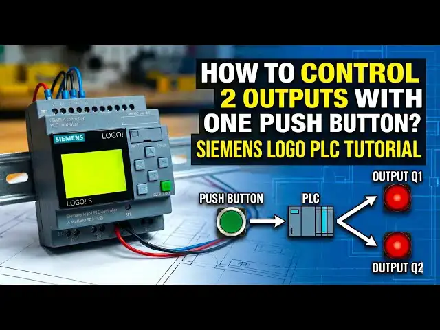
Learn how to control 2 outputs with one pushbutton using Siemens LOGO PLC programming.
👇FOLLOW US👇
WhatsApp Channel: https://whatsapp.com/channel/0029VaAbUecLNSa4rDPOV31o
Telegram Channel: https://t.me/+u3qORX5FKec1NjA1
Facebook Page: https://www.facebook.com/instrumentationtoolss/
LinkedIn Page: https://www.linkedin.com/company/instrumentationtools/
YouTube Channel: https://youtube.com/instrumentationtools?sub_confirmation=1
#SiemensLOGO #LOGOPLC #PLCProgramming #IndustrialAutomation #PLCTutorial #ControlLogic #PushButtonControl #AutomationBasics #PLCLearning #electricalautomation
Tags:
Siemens LOGO PLC, LOGO PLC programming, Siemens LOGO tutorial, PLC push button logic, control two outputs PLC, one push button two outputs, PLC ladder logic example, LOGO PLC basics, Siemens PLC beginners, PLC control logic, industrial automation PLC, LOGO soft comfort, PLC training video, PLC logic design, automation control example, electrical automation PLC, simple PLC logic, PLC output control, PLC input output logic, PLC practical example
Show More Show Less View Video Transcript
0:07
hello everyone myself
0:09
badas today in this video I will discuss
0:14
about one interesting
0:17
example here there are two outputs and
0:21
one input so we have to control two
0:23
outputs with one push
0:26
button if the push button is pressed and
0:30
released immediately then output one
0:33
will be on or off if the output one is
0:38
in off State then it will be in on state
0:42
okay again if the push button is pressed
0:45
and released immediately for a short
0:47
moment then again the output one changes
0:51
its state initially it is in off State
0:55
so it will be in on for every time if
0:59
you press and release the push button
1:01
the output one will be in on state to
1:04
off State or off state to on state it
1:06
will change okay the default start first
1:10
time state is off State remember
1:14
that if the push button is pressed and
1:18
it is hold for 5 seconds or more than 5
1:22
seconds then the output two will be
1:25
controlled the the default state are the
1:29
first time state is in off State when we
1:32
press the input push button for 5
1:34
seconds press and hold for 5 seconds
1:37
then output two will be
1:40
on again it is released and again the
1:43
push button is pressed for 5 seconds
1:46
then output two will be
1:49
off in simple terms if the push button
1:52
is pressed and released
1:54
immediately then output one will be in
1:57
control State output one will be
1:59
controll
2:00
okay if the push button is pressed and
2:04
hold for 5 seconds or more than 5
2:07
seconds then output two will be
2:09
controlled okay so the main objective
2:13
here is we have only one push button but
2:16
we are independently controlling two
2:22
outputs okay the output one state and
2:25
output two State doesn't matter only
2:28
depends on the push
2:31
button uh timing how much time it is
2:35
pressed depends on it the outputs will
2:38
be controlled
2:40
independently okay so pause the video
2:44
here and try to solve this logic you
2:47
have one input which is push button and
2:51
two outputs digital outputs with one
2:54
input you have to independently control
2:57
two outputs try to solve this logic
3:02
okay now I will explain the program I
3:05
will go to the
3:08
software I will take one
3:18
input and I will take two
3:25
outputs I will add the
3:27
comment this is my push
3:31
button
3:34
okay and q1 is
3:37
my output
3:42
one and Q2 is output
3:52
two
3:55
okay so for controlling each output I
3:58
will take one pulse relay block okay so
4:04
go down scroll down and select pulse
4:13
relay and give the block name false
4:19
relay and for second one also give the
4:22
block
4:23
name now I will connect the output of
4:26
pulse relay to the output one similarly
4:30
for second pulse relay also connect
4:33
output
4:37
two now for output two I need one timer
4:41
on delay timer after 5 Seconds only the
4:45
output two will be controlled that is
4:48
why I taken one on delay
4:54
timer okay and sell at okay 5 Seconds
5:02
okay now connect the push button to the
5:05
on delay timer
5:06
input and the output of on delay timer
5:11
connect to the pulse
5:17
relay the output two program is
5:20
completed now we have to make the
5:24
program for the output one now go to
5:28
basic functions
5:30
and
5:31
select nand Edge falling Edge remember
5:35
that we have to take falling Edge block
5:39
the arrow must be in down side and take
5:42
one end block
5:48
also these two are important blocks
5:52
here give
5:53
the block name
5:56
nand falling Edge
6:02
okay and this one is I'll just enter and
6:07
click
6:08
okay now connect push button to the
6:13
first input of the falling Edge land
6:16
block and connect the output of the
6:19
block to the first input of and block
6:23
and connect the end output to the pulse
6:26
relay input trigger
6:48
okay now connect the output of on delay
6:52
timer to the nand falling Ed lost input
7:00
again similarly connect on delay timer
7:02
output to the
7:05
end last input fourth input
7:19
okay now add not
7:23
input I mean this on delay timer is
7:27
there right two inputs connected here
7:29
here just add the not gate double click
7:31
here on the line one bubble will appear
7:35
that means not is added again here also
7:38
double click bubble will come not is
7:42
added now the program is completed
8:13
just adjusting these
8:16
lines for your simulation purpose there
8:18
is no need to
8:25
adjust now open the PLC Hardware
8:41
and download the program transfer PC to
8:47
logo if you don't have the hardware with
8:50
you do the simulation and test the logic
8:58
okay yes
9:01
program is
9:11
downloading now I will go to the online
9:21
mode sent IP and click
9:25
okay also follow our YouTube channel
9:29
social media networks you will receive
9:32
more updates in
9:36
future okay now we will test the
9:39
logic I will press the input i1c what
9:43
happens one time press and releaseed
9:47
immediately the output one is in on
9:49
state output one is in on state again I
9:52
will press the input i1 and again I will
9:54
release
9:56
immediately output one off again press
9:59
and release output one on press and
10:03
release off press and
10:05
release what happens if you press and
10:08
release
10:09
immediately what
10:12
happens the output one is
10:15
in switching to on State and off State
10:19
accordingly as per the input push
10:26
button okay
10:30
if you see for the output
10:33
two if I press the push button and fold
10:36
for 5 seconds are more than 5 Seconds
10:39
the on Del timer will be started now it
10:41
is zero see what happens timer started
10:44
after 5 Seconds it will be
10:46
on then pulse relay output will be on Q2
10:50
will be
10:50
on the pulse relay output will change to
10:54
on state to off State or off state to on
10:57
state every time the input changes its
11:00
state from 0 to 1 that is why if I press
11:03
it again the input i1 for 5 seconds
11:06
after 5 Seconds the delay timer will be
11:09
on that means pulse relay input is
11:12
received already previously it is an on
11:15
state now it makes output off if again I
11:19
will press the input i1 for 5 seconds
11:21
then again on delay timer will be on
11:24
after 5 Seconds puls Rel received it
11:27
input again output is in on
11:31
state the output to you can easily
11:33
understand there is not that much logic
11:35
is not
11:37
there see timer is running 3 seconds now
11:41
I will release the push button before 5
11:44
Seconds what happens Q2 there is no eff
11:48
but q1 is in on
11:50
state
11:54
okay now we will discuss the the program
11:58
part is is
12:00
completed output two is very clear just
12:03
push button timer pulse relay
12:08
output you have to understand output One
12:12
Step logic
12:13
only here the nand falling AG block and
12:17
end block are important okay we taken
12:21
nand falling AG because we considered
12:25
the push button release State for the
12:28
control of output
12:30
one observe I will
12:34
press
12:36
the push
12:37
button okay I will press the push
12:41
button and again release it when the
12:45
output changed
12:47
State when I press the push button at
12:50
that time there is no
12:52
change here when we release the push
12:55
button the release time is considered
12:58
for that Purp first we take an land
13:01
falling Edge
13:05
okay if you if I press the input i1 the
13:08
output one will not be on see if I
13:11
release the input i1 before 5 seconds
13:15
then the output one will be
13:19
on for that purpose we take an N falling
13:24
Edge
13:26
okay and here
13:29
this output one will be controlled okay
13:32
will be switched on State and off state
13:34
only
13:37
when the output two is not controlled
13:41
okay if push button is pressed for 5
13:44
seconds or more than 5 seconds then that
13:47
signal must be used for only for output
13:50
two if the push button is pressed for
13:53
momentary are less than 5 seconds then
13:56
that signal must be used for output one
14:00
for that purpose we need one
14:02
interlock okay that is why the on delay
14:06
timer output is connected to n falling
14:08
Edge and end
14:11
block so most uh this is the
14:14
concept and use the same logic simulate
14:19
the logic and explain why we added the
14:23
bubble not gate and why we used the
14:27
combination of nand following H and end
14:31
block with not
14:34
gates for the output one
14:37
functionality so explain or share with
14:40
us through the comment section
14:43
okay why the not gate and why the combo
14:48
of nand falling Edge and end block this
14:51
is the first question and the second
14:54
task is or second question
14:56
is here we use n fall langage and end
15:01
blocks right now try to simulate or try
15:04
to achieve this same program or
15:08
functionality using some other blocks
15:12
combination instead of nand falling Ag
15:15
and end block
15:19
okay try to do the same program using
15:22
other blocks program means I'm talking
15:25
about only these two
15:26
blocks nand and and replace these blocks
15:31
with some other blocks if you're able to
15:33
achieve some same functionality share
15:36
with us how you achieved
15:38
this remember when you are learning the
15:41
PLC
15:42
programming it doesn't matter how many
15:45
blocks you're going to use you can use
15:48
10 blocks 20 blocks no problem just
15:54
use any number of blocks and try to
15:57
achieve the
15:59
functionality try to achieve the
16:02
objective when you have good experience
16:05
with the
16:06
programming then you can think about the
16:09
optimization of the blocks or using less
16:13
number of blocks to achieve the output
16:15
okay when you are learning the
16:18
programming it doesn't matter how many
16:20
blocks you're going to use the first
16:23
thing is you have to solve the
16:25
problem and when you are practicing when
16:29
you achieved some experience with the
16:31
PLC programming then you can think about
16:34
the optimization okay some people
16:37
directly go for the
16:39
optimization okay the optimization is
16:41
not required when you are a
16:44
beginner this is one of the tip I want
16:47
to give with you thank you I will meet
16:50
you in the next video
#Jobs & Education