0:00
In this video, I will show you inside
0:04
So, this is our heart communicator.
0:07
Using heart communicator, you can do the
0:10
configuration of a device. It may be a
0:13
heart based instrument or foundation
0:16
field bus based instrument.
0:18
In this case, we are using a foundation
0:21
field bus based device. So, we have to
0:25
field bus menu. See, this is the default
0:29
menu of a heart communicator. As we are
0:32
using a foundation field bus based
0:35
we have to go to the field bus menu.
0:41
And I'll press enter.
0:44
This is our field bus menu and we have
0:50
Wait for some time. Again, press enter.
0:55
We have to go to online and then we can
1:00
foundation field bus instruments on the
1:02
network or on the segment. See, there is
1:05
a warning. There could be a database
1:09
It is saying that there is a database
1:11
mismatch between your host system
1:13
database. It is fine. You can press S.
1:17
No issue. And then it will go to the
1:22
See, it will take some time. It is a
1:24
acyclic communication.
1:27
It is having the least priority. That
1:30
means it will take time.
1:33
number of devices, length of the cable,
1:37
so many parameters. Okay?
1:41
now this is live list. Okay? Field bus
1:46
When you connect your heart communicator
1:51
you can access or you can view all
1:54
devices connected to the network.
1:57
Remember, here network means the
2:00
respective foundation field bus segment
2:03
or foundation field bus junction box or
2:07
foundation field bus trunk cable.
2:10
Let's say there are 30 foundation field
2:13
bus junction boxes. That means you have
2:15
30 networks, 30 segments.
2:19
So, when you connect your heart
2:21
communicator to your field instrument,
2:23
you can access the devices related to a
2:28
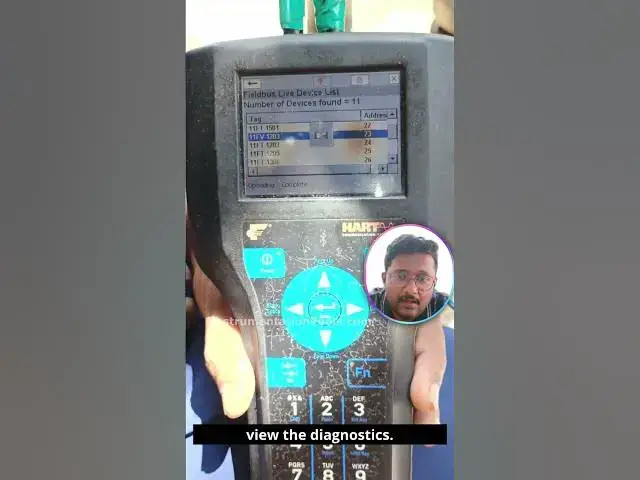
Now, we will see this heart communicator
2:32
You can see the number of devices found.
2:37
We have complete 11 instruments are
2:39
connected to this junction box.
2:42
You can see here LAS, link active
2:47
So, we know that our foundation field
2:50
bus module or card is called as link
2:54
active scheduler. You can see this
2:57
clearly. ALF111-4-14.
3:05
foundation field bus IO card
3:08
in Yokogawa DCS systems.
3:13
And remember, every device have a device
3:16
address in foundation field bus.
3:19
For this LAS, the device address is 20.
3:25
two LAS cards, right?
3:28
We have two foundation field bus cards
3:31
in our DCS system for backup purpose,
3:34
for redundancy purpose.
3:39
you can see its number is
3:47
And its address is 21.
3:51
And now we are seeing the live list.
3:53
Now, I will show you all the instruments
3:57
connected to this network. And you can
3:59
see the tag name of the instrument and
4:01
the device address. Okay?
4:04
This is a flow transmitter, flow valve,
4:08
flow transmitter again, level
4:10
transmitter, temperature transmitter,
4:12
pressure transmitter. Okay? And you can
4:15
see the device address also, the node
4:16
address or device address.
4:19
So, level transmitter, temperature
4:23
And then field communicator.
4:26
So, I connected my heart communicator to
4:30
So, this heart communicator also have
4:34
some temporary node address. The link
4:37
active scheduler will assign a temporary
4:39
node address or device address to a
4:42
heart communicator. In this case, it is
4:45
252 is a temporary address assigned by
4:48
the link active scheduler. Okay?
4:51
For my heart communicator.
4:55
And again, I will show you all my
4:56
instruments connected in the junction
4:59
Remember, you can access any device from
5:03
this list. You can enter and you can
5:06
view all the configurations. You can see
5:09
diagnostic messages or you can do the
5:11
calibration of any instrument by
5:14
connecting to any instrument on a
5:19
segment. Now, what is the tag name of my
5:22
control valve? It is 11 FV1203.
5:26
The device address is 23. For this
5:29
control valve, I want to do the
5:33
But remember, by connecting to your
5:35
heart communicator in a segment at any
5:39
place, at any instrument, you can access
5:42
all instruments parameters.
5:45
You can view the diagnostics. You can
5:47
change the configuration parameters or
5:49
you can view the configuration
5:52
Okay? You can do anything at any place.
5:58
I will press enter. And then it will go
6:06
I'm pressing enter. Again, it will take
6:08
time. See, uploading or reading status.
6:12
It will take time. Foundation field bus
6:14
for acyclic communication,
6:17
it may take time. You have to wait. See,
6:20
let's see how much time it will take to
6:22
enter into the device so that we can see
6:25
the configuration parameters or we can
6:28
view the diagnostics.
6:34
The time may vary. It is not like every
6:39
See, the time may vary. It depends on
6:44
segment healthiness status also or
6:46
number of devices connected to your
6:51
And its physical properties like cable
7:09
We almost entered into the configuration
7:16
See, now we are in inside the
7:22
This is a Metso valve positioner.
7:27
Inside your field bus settings, you will
7:31
find different blocks like resource
7:33
block, transducer block, analog input
7:36
block, analog output,
7:39
digital input, digital output, PID, etc.
7:44
In this case, this is analog output,
7:47
It is using a digital communication, but
7:50
the block names we are calling as analog
7:52
input, analog output, okay, based on the
7:58
It doesn't mean that we are using a 4 to
8:00
20 mA signal. We are using only digital
8:03
communication between
8:04
your foundation field bus instrument and
8:09
Thank you. I will meet you in the next